Indice
RosettaCNC Probe A - Installation and Maintenance Manual

Dear Customer,
Thank you for purchasing this product. This document aims to collect all the necessary information for the installation and use of this accessory.
Need assistance?
Post in the forum on the website RosettaCNC.com or send an email to: support@rosettacnc.com, the RosettaCNC development team will be happy to respond promptly.
I diritti d'autore di questo manuale sono riservati. Nessuna parte di questo documento, può essere copiata o riprodotta in qualsiasi forma senza la preventiva autorizzazione scritta. RosettaCNC Motion® non presenta assicurazioni o garanzie sui contenuti e specificatamente declina ogni responsabilità inerente alle garanzie di idoneità per qualsiasi scopo particolare. Le informazioni in questo documento sono soggette a modifica senza preavviso. RosettaCNC Motion® non si assume alcuna responsabilità per qualsiasi errore che può apparire in questo documento. RosettaCNC Motion® è un marchio registrato.
Information
| |
||||
| Document: | MIMROSETTACNCProbeA | |||
|---|---|---|---|---|
| Description: | Installation and Maintenance Manual | |||
| Link: | http://wiki.rosettacnc.com/doku.php/hardware:rosettacncboard:mimrosettacncprobea | |||
| Document Release | Hardware Version | Description | Notes | Date |
| 01 | 01 | New manual | / | 13/12/2021 |
1. Introduction
1.1 General Description
5-axis touch-trigger probe to be mounted on the spindle, robust and compact.
- Black anodized 6061-T6 aluminum body and stainless steel shaft
- Anti-oxidation electrical system covered with dielectric fluid
- Modular construction
- Dust and splash-proof from all directions
- Normally closed internal switching contacts
- Shielded flexible cable with quick connector
- Each probe is tested before shipping
- Concentricity calibration with 3 or 4 screws, Allen key included. Optically calibrated before shipping.
- Probe tip with standard M3x0.5 thread
- Stainless steel shank: D = 7.0 mm, H = 20 mm
- Unit dimensions without stylus: Ø = 40mm, H = 38.5mm
- Maximum safe movement: 8mm radial (with 31mm tip), 5mm axial
- Adjustable: 4-side set screws with included Allen key
- Operating principle: breaks contact in case of a touch event
- Included cable length: 3 m (with connected connector)
- Protection class: IP64 (sealed with silicone gaskets against dust and liquid splashes)
- Base material: black anodized 6061-T6 aluminum and stainless steel
- Weight: 160 g
- Actuation force: axial ~ 5 N, radial 1 N
- Electrical contacts in tungsten carbide with anti-oxidation dielectric fluid
- Repeatability: 2µm
1.2 Symbols Used in the Manual
Useful information and suggestions
Warnings, failure to follow these warnings may lead to improper operation or damage to the device
Potential danger and possible risk of injury
1.3 Package Contents
- n.1 Probe
- n.1 Cable
- n.1 Allen key

1.4 Product Identification
Based on the product Order Code, its exact characteristics can be determined.
Verify that the product characteristics match your needs.
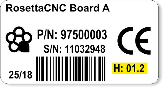
1.4.1 Product Label

- a - Codice di ordinazione
- b - Data di produzione: indica la settimana e l'anno di produzione
- c - Part number: codice univoco che identifica un codice d'ordinazione
- d - Serial number: numero di serie dello strumento, unico per ogni pezzo prodotto
- e - Versione hardware: versione e release dell'hardware
1.4.2 Order Code
The RosettaCNC Probe A is available in the following versions:
| Part number | Model | Description |
|---|---|---|
| 94030020 | RosettaCNC Probe A | Precision = 0.01mm, complete with stylus, ruby, and cable |
2. Mechanical Installation
2.1 Dimensions

Dimensions in mm
3. Connections
3.1 Cable Description
| Color | Function |
|---|---|
| White | NC Contact |
| Shield | Common |
3.2 Connection to RosettaCNC Board A
This Probe model is compatible only with RosettaCNC Board A from hardware version 1.2 onwards.
| Probe | Connector CN9 on RosettaCNC Board A | ||
|---|---|---|---|
 | White | 4A | 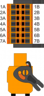 |
| 7A - Connect to 7B | |||
| 7B - Connect to 7A | |||
| Shield | Connect to +24Vdc | ||
PROBE on CN9

3.3 Connection to RosettaCNC Board B
| Probe | Connector CN16 on RosettaCNC Board B | ||
|---|---|---|---|
| | White | 4A | |
| 7A - Connect to 7B | |||
| 7B - Connect to 7A | |||
| Shield | Connect to +24Vdc | ||
PROBE on CN16
4. Settings
To use the Probe, it is necessary to correctly set the values highlighted in the following figure (in the panel “RosettaCNC Board Settings→Digitizer”):

For the model described here, the correct setting is NC.
With this probe, it is possible to perform surface digitization or use G-code probing functions.
4.1 Surface Digitization
For this function, some parameters must be set in the “RosettaCNC Board Settings→Digitizer” panel. Then the function is started from the “Functions→3D Scanning with Probe” panel.
4.2 G-Code Probing Functions
These functions are activated using G38 codes. See the section probing.
5. Contributions
We thank in advance all those who wish to contribute to improving this documentation by reporting inaccuracies or additional content. Write to: support@rosettacnc.com