Table of Contents
8. Coordinate Systems
RosettaCNC G-Code has some powerful features that allow the user to transform coordinates in order to create complex shapes with just a few lines.
8.1 The 5 Steps G-Code Coordinate Pipeline
Coordinates are handled in 5 different steps/levels, every step influences all the steps at is right.
8.1.1 Step 1: Unit Conversion
The first calculation involves handling the length units used your program that can be mm or inches as defined by G20 and G21.
8.1.2 Step 2: Conversion from Relative or Polar to Absolute Coordinates
The following step involves converting relative or polar coordinates to absolute coordinates.
- Relative coordinates are enabled with G90 and disabled with G91
- Polar coordinates consist in specifying a radius and an angle instead of X and Y Cartesian coordinates and are enabled by G15 and disabled by G16. When polar coordinates are enabled X is the radius relative to the current position and Y is the angle. (For further explanations see Cartesian & Polar Coordinates
8.1.3 Step 3: Offsets: G52, G54 and G92
RosettaCNC supports three different kinds of offsets:
- Work Offsets define different places a part zero may be. They're typically handled via G54, G55, …, .
- Local Offsets are defined by G52. They make it easily to temporarily move the zero to a new place. For example, the center of a bolt circle while you're busy drilling it so you don't have to offset each hole from part zero.
- Workpiece Coordinate System setting set using G92 is another facility for setting offsets.
Examples
To update the WCS during a G-code program
#<_wcs.index_> = 1 ; Set a variable to store the desired WCS index.
                   ; Notes:
                   ; - index is 1 for G54, 2 for G55, ...
                   ; - the index of the WCS currently in use is stored in #5220
; The following command set the WCS G54 to have offsets X=10 Y=20 Z=30
G10 L2 P#<_wcs.index_> X10 Y20 Z30
8.1.4 Step 4: Scaling and Mirroring: G51
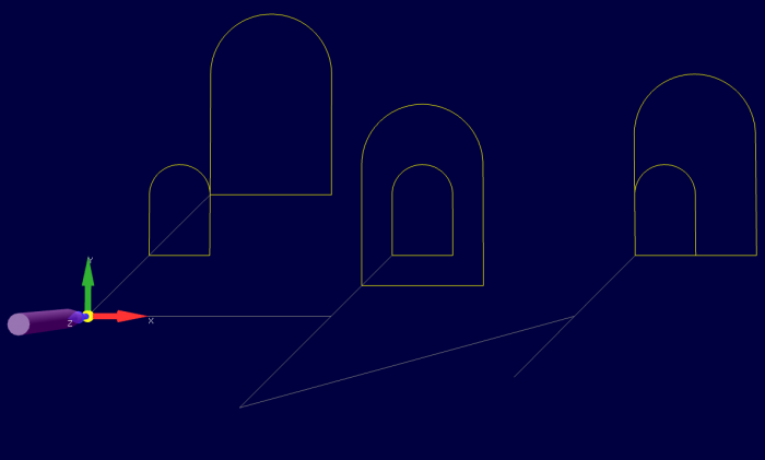
A G51 applies scaling/mirror to all positions, lines, and arcs following this G-code until a G50 are entered.
A different scaling factor can be specified for every axis using I (for X axis) J (for Y axis) and K (for Z axis) while parameter P can be used if scaling factors are the same for all the axes.
The X, Y, and Z parameters are the coordinates of the scaling center. If the scaling center is not specified, the default scaling center is the current cutter position (not the current origin).
To mirror, enter a negative value for the scaling factor.
Notes:
- If the arc radius was specified with R, the radius will be scaled by the larger of the two circular plane scale factors. The result will be a circular arc between the scaled arc start and the scaled arc end.
- If the arc center was specified with I, J, and/or K, the centres will be scaled by the appropriate axis scale factors. The result will be a circular arc from the scaled arc start, around the scaled center, and usually with a line from the end of the circular arc to the scaled arc end.
- In no case can an ellipse be generated using scaling.
( © 2019 RosettaCNC Motion                                       )
( file name: scaling.ngc                                         )
( G-code scaling example that uses G50 and G51                   )

G21 G40 G49 G90 G54 G50 G69

M98 P1 ; Normal window
G0 X0 Y0
G59
G0 G90 x0 y0 z0
G51 P2 ; Scaling center is X0 Y0 Z0
M98 P1 ; Scaled window
G50

; Move to the right using G55 system to avoid plot overlapping
G10 L2 P2 x40
G55

G0 G90 x0 y0 z0
M98 P1 ; Normal window
G51 X15 Y15 P2 ;
M98 P1 ; Scaled window
G50

G10 L2 P2 x0
G54

; Move to the right using G55 system to avoid plot overlapping
G10 L2 P3 x80
G56

G0 G90 x0 y0 z0
M98 P1 ; Normal window
G51 X10 Y10 P2 ;
M98 P1 ; Scaled window
G50

G10 L2 P3 x0
G54
M2

( Gothic window )
O1
	F20. S500 ;
	G00 X10 Y10
	G01 X20
	Y20
	G03 X10 R5 ;or I-5 J0
	G01 Y10
	G00 X0 Y0
M99
8.1.5 Step 5: Rotation: G68
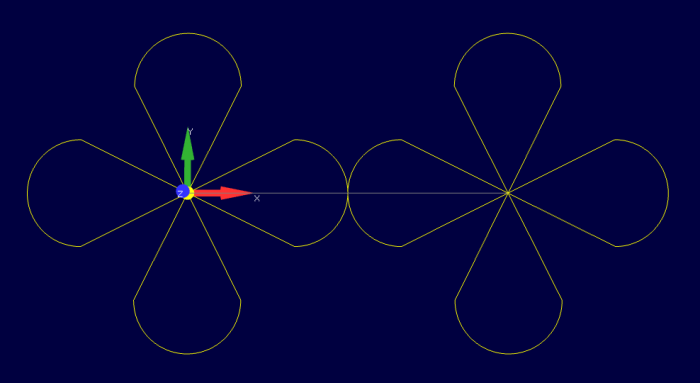
With G68, you can rotate the coordinates an arbitrary number of degrees about an arbitrary center.
The X, Y, and Z parameters are the coordinates of the scaling center.
If the rotation center is not specified, the default rotation center is the current cutter position (not the current origin).
( © 2018 by RosettaCNC Motion                                                     )
( file name: rotation.ngc                                                         )
( G-code rotation using G68 and G69                                               )
G54 F1000 G90 G17
G0 X0
M98 P2 L1
G0 X300
M98 P2 L1
G0 X0 Y0
M30

O2 ; XY Draw an entire flower with 4 petals
	#1 = 0
	WHILE [#1 LT 4] DO1
		#1 = [#1 + 1]
	    #2 = [#1 * 90]
		M98 P1 L1
		G68 R#2 ; The current point is set as origin if X,Y
		        ; (or A,B using HAAS notation plane independent) are not specified.
	END1
	G69 ; Reset origin offsets and rotation
M99

O1 ; Draw a simple petal in the XY plane
    G91 ; switch to relative
	G01 X-50 Y100.0
	G02 X100 Y0 I50
	G01 X-50 Y-100
	G90 ; switch to absolute
M99


