Indice
4. Cutter compensation
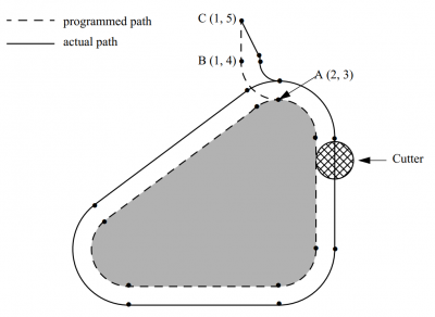
The cutter radius compensation capabilities of the Interpreter enable the programmer to specify that a cutter should travel to the right or left of an open or closed contour composed of arcs of circles and straight line segments, all planes are supported XY, YZ and XZ.
4.1 G41, G42 Cutter Compensation
G41 <D> <I>left of programmed pathG42 <D> <I>right of programmed path
Notes
D- tool numberI- dynamic radius offset- The D word is optional; if there is no D word the radius of the currently loaded tool will be used (if no tool is loaded and no D word is given, a radius of 0 will be used).
- The I word is optional; if there is I word the resulting radius will be: “table diameter value” / 2 - “I value”.
- If supplied, the D word is the tool number to use. This would normally be the number of the tool in the spindle (in which case the D word is redundant and need not be supplied), but it may be any valid tool number.
- It is an error if:
- The D number is not a valid tool number or 0.
- Cutter compensation is commanded to turn on when it is already on.
4.2 G41.1, G42.1 Dynamic Cutter Compensation
G41.1 D <L>(left of programmed path)G42.1 D <L>(right of programmed path)
Notes
D- cutter diameterL- tool orientation (see lathe tool orientation)- G41.1 & G42.1 function the same as G41 & G42 with the added scope of being able to program the tool diameter. The L word defaults to 0 if unspecified.
- It is an error if:
- The YZ plane is active.
- The L number is not in the range from 0 to 9 inclusive.
- The L number is used when the XZ plane is not active.
- Cutter compensation is commanded to turn on when it is already on.
4.3 Tool compensation entry options
- Three compensation entry option are supported:
- NIST
- The default NIST mode.
- Easy Lead-In
- Delays the first movement of the entry move until the following line or arc is specified.
- When the second entry motion is specified it performs the entry move to a position tangent to the beginning of the second line or arc.
- This option works well with some CADs such as Fusion360 indeed not gouging errors are generated.
- Normal
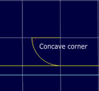
- It is the only option that can handle concave corners and concave arcs.
The Easy lead-In option is needed when a concave corner is present between the first and the second move that is part of the Lead-in.
Common Cutter Radius Compensation Errors
When the first two options are selected and cutter radius compensation is on, it must be physically possible for a circle whose radius is
the half the diameter given in the tool table to be tangent to the contour at all points of the contour.
In particular, the Interpreter treats concave corners and concave arcs into which the circle will not
fit as errors, since the circle cannot be kept tangent to the contour in these situations.
This error detection does not limit the shapes which can be cut, but it does require that the programmer specify the actual shape to be cut (or path to be followed), not an approximation.
In both examples, the line represents a contour, and the circle represents the cross section of a tool following the contour using cutter radius compensation (tangent to one side of the path.)
4.4 Examples
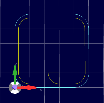
4.4.1 Easy Lead-in
( © 2018 by RosettaCNC Motion        )
( file name: cutter_compensation.ngc )

G21 G40 G49 G90 G54 G50 G69
G0 x10y0z0
T0 M6
F2000
( Non compensated square )
M98 P1000

G0 x30y10z0
T1 M6
G41 D1
( Lead- in moves )
G1X20Y10
G3X30Y0I10J0
( Compensated square )
M98 P1000
G40
G0X30y10z0
M30

( Square with rounded corners )
O1000
    G1X40
    G3X50Y10I0J10
    G1Y40
    G3X40Y50I-10J0
    G1X10
    G3X0Y40I0J-10
    G1Y10
    G3X10Y0I10J0
    G1X30
M99
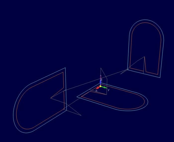
4.4.2 Auto
( © 2018 by RosettaCNC Motion                           )
( file name: automatic_compensation.ngc                 )
( G-code with cutter comensation example in all planes  )
( Note: for a real work the cutter compensation lead-in )
(       move should be added manually.                  )
G17 G21 G40 G49 G90 G54 G50 G69

; XY plane
G17
G00 Z50
G00 X50 Y50

M6 T0
F1000. S500
G00 Z10
M98 P1 ; Normal window

G00 X50 Y50
M6 T3
F1000. S500
G01 Z10
G41
M98 P1 ; Compensated window
G40

G52 X150
G00 X0 Y0 Z0

; XZ Plane
G18
G00 Y50
G00 Z50 X50

M6 T0
G00 Y10
M98 P2 ; Normal window

G00 Z50 X50
M6 T3
F1000. S500
G01 Y10
G41
M98 P2 ; Compensated window
G40

G52 X-150
G00 X0 Y0 Z0

; YZ Plane
G19
G00 X50
G00 Y50 Z50

M6 T0
G00 X10
M98 P3 ; Normal window

G00 Y50 Z50
M6 T3
F1000. S500
G01 X10
G41
M98 P3 ; Compensated window
G40

M2

O1 ; Gothic window XY
    G91
    G01 Y-50
	X50
	Y100
	G03 X-100 R50
	G01 Y-100
	X50
	G90
M99

O2 ; Gothic window XZ
    G91
    G01 X-50
	Z50
	X100
	G03 Z-100 R50
	G01 X-100
	Z50
	G90
M99

O3 ; Gothic window YZ
    G91
    G01 Z-50
	Y50
	Z100
	G03 Y-100 R50
	G01 Z-100
	Y50
	G90
M99


