This is an old revision of the document!
AN011 - Position control loop - configuration nr.01
The purpose of this application note is to illustrate a simple guide for using RosettaCNC board B with position control loop.
1. What is the configuration nr.01
The configuration nr.01 consists of a firmware where I/O are set to control max 5 axes. For every axis there is an analog output to control servodrive velocity, and a quadrature encoder for position feedback. Spindle is driven by analog output.
Analog outputs to control servodrive velocity are configured from -10 volts to +10volts.
2. Necessary material
We need:
- A RosettaCNC board B purchased with Position control loop option (see “Order Code” “Motor control type” at value A).
- The I/O Expansion option “1 = CN21-CN22-CN24” is needed to control more than 3 axes.
3. Preliminary operations
- Install the latest version of the RosettaCNC software
- Download the attached sfs file and copy it to %appdata%\RosettaCNC-1\firmware.
- Open the “Board firmware manager” panel and start to download the firmware named RosettaCNC-BA-01.
- Download the rosettacnc1.ini file and overwrite the same file in %appdata%\RosettaCNC-1\firmware\Machine\RosettaCNC (or the machine name you are using). Take care to close the software before overwrite the file!
At the end connect RosettaCNC software to the board.
In this application note We consider all settings as the default of the software installer.
4. Signal mapping
Differences from the standard board documentation are described here.
| Pin | Description |
|---|---|
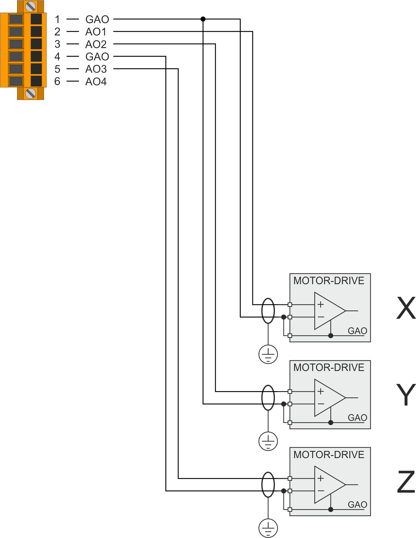
| CN12 pin 2 | Axis X analog output |
| CN12 pin 3 | Axis Y analog output |
| CN12 pin 5 | Axis Z analog output (-10 +10 volts) |
| CN12 pin 6 | Spindle speed (0 +10 volts) |
| Pin | Description |
|---|---|
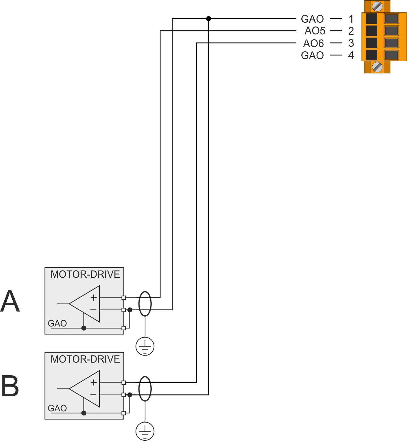
| CN24 pin 2 | Axis A analog output |
| CN24 pin 3 | Axis B analog output |
| Pin | Description |
|---|---|
| CN14 | Axis X position feedback or MPG4 |
| CN15 | Axis Y position feedback or MPG3 |
| CN16 | Axis Z position feedback or MPG2 |
| CN17 | HandWhell or MPG1 |
| CN21 | Axis B position feedback |
| CN22 | Axis A position feedback |
4.0.1 CN14
| CN14 | Morsetto | MPG4 | ENCODER ASSE X | |||
|---|---|---|---|---|---|---|
| Simbolo | Descrizione | Simbolo | Descrizione | |||
 | 1A | 5Vdc | Uscita +5Vdc | 5Vdc | Uscita +5Vdc | |
| 2A | PHA1 | Encoder Asse X (Logica 24V Push-Pull) |
||||
| 3A | PHB1 | |||||
| 4A | Z1 | |||||
| 5A | Collegare con 5B | Collegare con 5B | ||||
| 6A | Collegare con 6B | Collegare con 6B | ||||
| 7A | 0V | Comune “0V” dell'ingresso encoder Asse X Collegare con 7B |
||||
| 1B | 5Vdc | Uscita +5Vdc | ||||
| 2B | PHA | Fase A | PHA1+ | Encoder Asse X (Logica 5V Linedriver) |
||
| 3B | PHB | Fase B | PHB1+ | |||
| 4B | Z1+ | |||||
| 5B | Collegare con 5A | PHA1- | ||||
| 6B | Collegare con 6A | PHB1- | ||||
| 7B | Z1- | |||||
4.0.2 CN15
| CN15 | Morsetto | MPG3 | ENCODER ASSE Y | |||
|---|---|---|---|---|---|---|
| Simbolo | Descrizione | Simbolo | Descrizione | |||
| | 1A | 5Vdc | Uscita +5Vdc | 5Vdc | Uscita +5Vdc | |
| 2A | PHA2 | Encoder Asse Y (Logica 24V Push-Pull) |
||||
| 3A | PHB2 | |||||
| 4A | Z2 | |||||
| 5A | Collegare con 5B | Collegare con 5B | ||||
| 6A | Collegare con 6B | Collegare con 6B | ||||
| 7A | 0V | Comune “0V” dell'ingresso encoder Asse Y Collegare con 7B |
||||
| 1B | 5Vdc | Uscita +5Vdc | ||||
| 2B | PHA | Fase A | PHA2+ | Encoder Asse Y (Logica 5V Linedriver) |
||
| 3B | PHB | Fase B | PHB2+ | |||
| 4B | Z2+ | |||||
| 5B | Collegare con 5A | PHA2- | ||||
| 6B | Collegare con 6A | PHB2- | ||||
| 7B | Z2- | |||||
4.0.3 CN16
| CN16 | Morsetto | MPG2 | ENCODER ASSE Z | |||
|---|---|---|---|---|---|---|
| Simbolo | Descrizione | Simbolo | Descrizione | |||
| | 1A | 5Vdc | Uscita +5Vdc | 5Vdc | Uscita +5Vdc | |
| 2A | PHA3 | Encoder Asse Z (Logica 24V Push-Pull) |
||||
| 3A | PHB3 | |||||
| 4A | Z3 | |||||
| 5A | Collegare con 5B | Collegare con 5B | ||||
| 6A | Collegare con 6B | Collegare con 6B | ||||
| 7A | 0V | Comune “0V” dell'ingresso encoder Asse Z Collegare con 7B |
||||
| 1B | 5Vdc | Uscita +5Vdc | ||||
| 2B | PHA | Fase A | PHA3+ | Encoder Asse Z (Logica 5V Linedriver) |
||
| 3B | PHB | Fase B | PHB3+ | |||
| 4B | Z3+ | |||||
| 5B | Collegare con 5A | PHA3- | ||||
| 6B | Collegare con 6A | PHB3- | ||||
| 7B | Z3- | |||||
4.0.4 CN21
| CN21 | Morsetto | ENCODER ASSE B | ||
|---|---|---|---|---|
| Simbolo | Descrizione | |||
| | 1A | 5Vdc | Uscita +5Vdc | |
| 2A | PHA6 | Encoder Asse B (Logica 24V Push-Pull) |
||
| 3A | PHB6 | |||
| 4A | Z6 | |||
| 5A | Collegare con 5B | |||
| 6A | Collegare con 6B | |||
| 7A | 0V | Comune “0V” dell'ingresso encoder Asse B Collegare con 7B |
||
| 1B | 5Vdc | Uscita +5Vdc | ||
| 2B | PHA6+ | Encoder Asse B (Logica 5V Linedriver) |
||
| 3B | PHB6+ | |||
| 4B | Z6+ | |||
| 5B | PHA6- | |||
| 6B | PHB6- | |||
| 7B | Z6- | |||
4.0.5 CN22
| CN22 | Morsetto | ENCODER ASSE A | ||
|---|---|---|---|---|
| Simbolo | Descrizione | |||
| | 1A | 5Vdc | Uscita +5Vdc | |
| 2A | PHA5 | Encoder Asse A (Logica 24V Push-Pull) |
||
| 3A | PHB5 | |||
| 4A | Z5 | |||
| 5A | Collegare con 5B | |||
| 6A | Collegare con 6B | |||
| 7A | 0V | Comune “0V” dell'ingresso encoder Asse A Collegare con 7B |
||
| 1B | 5Vdc | Uscita +5Vdc | ||
| 2B | PHA5+ | Encoder Asse A (Logica 5V Linedriver) |
||
| 3B | PHB5+ | |||
| 4B | Z5+ | |||
| 5B | PHA5- | |||
| 6B | PHB5- | |||
| 7B | Z5- | |||
5. Steps to make the machine operative
5.1 Enable axis and set parameters
- Open Board settings panel and enable the axis that the machine need.
- Set correct funtion to ESTOP inputs and other signals
- Open Advanced Parameter tab. from 1 to 60 and check if all are zero.
5.2 Check count direction
Move every motor shaft and check if count direction os ok. Count value is show in main RosettaCNC layout or in DRO panel (View→Show DRO Monitor)
5.3 Set appropriate position factor
Now for every axes set appropriate value of Pulse and Measure settings in order to count the linear movements in units.
5.4 Enable axes
Open Advanced Parameter tab. and set 3 and 4 (for every axes) if you need a servodrive enable outputs. Take care that servodrive now is enabled !!
5.5 Set DAC offset
For every axes set appropriate value to Advanced Parameter 2 to obtain that the axis don't move. Do this with a series of successive approximations until you arrive at the value where the count remains stationary.
5.6 Check motor direction
Consider that:
- Advanced Parameter nr1 is the Max velocity at 10volt analog output [mm/min]
- Axis tab Max velocity value is the rapid G0 axis velocity.
For our test we set the same value in Advanced Parameter nr1 and Axis tab Max velocity. For example 5000mm/min.
Set Advanced Parameter nr5 (Axis X - Feedforward [%]) to 100.0%
Now move axis in Jog at 5% jog override.
Please take care that this is a open loop movement and software limits can not protect again hardware collision
When move in jog check if motor movement is right with machine convention. If you need to reverse motor direction, please see the servodrive manual to do it.
5.7 Set Axis max velocity
Use the settings made during “Check motor direction”.
Now move axis in Jog at 10% jog override.
Please take care that this is a open loop movement and software limits can not protect again hardware collision
When move in jog at 10% read the velocity in DRP panel. If it is possible increase the Jog overrire. Read the velocity both forward and backward direction. At the end consider only the lowest value. Calculate the velocity that the axis will at 100%. This value is the Advanced Parameter nr1
Decrease this value by 5-10% and this is the max value that you can set in Axis tab Max velocity
5.8 Active Control loop
Now we have to activate position control loop.
Actually the control loop was already active, but the pgain parameter at zero value prevented any control.
Now we can't just activate the parameter, otherwise the axis could move dangerously.
Steps to do:
- Generate an Alarm (for example press ESTOP) and make sure that RosettaCNC have the alarm Active
- Set Advanced Parameter nr6 (Axis X - PID proportional gain) to 0.001
- Set Advanced Parameter nr8 (Axis X - Max following error [mm]) to a At a reasonable value, for example 20mm
- Close settings panel
- Reset RosettaCNC Alarm
- Now Control loop is active with a minimal gain.
- Try to move axis in Jog.
It could happen that an alarm appears by following error. Do not worry. Clears the alarm and slightly increases the value of the PID proportional gain parameter.
Now you have to try to move the axis in Jog and slightly increase the value of the PID proportional gain parameter until the axis at rapid speed moves well.
Never set values that are too high which cause the axis to oscillate.
5.9 Fine tune the threshold of following error
Set Advanced Parameter nr8 (Axis X - Max following error [mm]) to the value that is right for machine precision and that never generate alarm during rapid movements.
6. Note
- Each servodrive must be electrically connected so that by pressing the ESTOP button it can enter the safe state without intervention by the RosettaCNC product. The safety state can be reached by interrupting the electrical energy, or by using the STO contacts if provided.
- When the ESTOP button is pressed, the RosettaCNC product is only informed of the presence of an alarm.
- If a servodrive is used to support a mechanical part that can be dangerous in the event of a power failure, the motor must be equipped with a brake and this brake must intervene automatically with a command from the servodrive. The RosettaCNC product cannot manage the brake command.
- Each servodrive must use a user output of the RosettaCNC product (therefore a digital input of the servodrive) to enable motor control. Only when the user output is active the servodrive use the analog output to determine the motor rotation speed. To configure this user output use the Advanced Parameter nr3 (Axis X - User output to enable servodrive). Also set a typical value of 500msec in Advanced Parameter nr4.
7. Connection examples
7.1 CN12
7.2 CN24
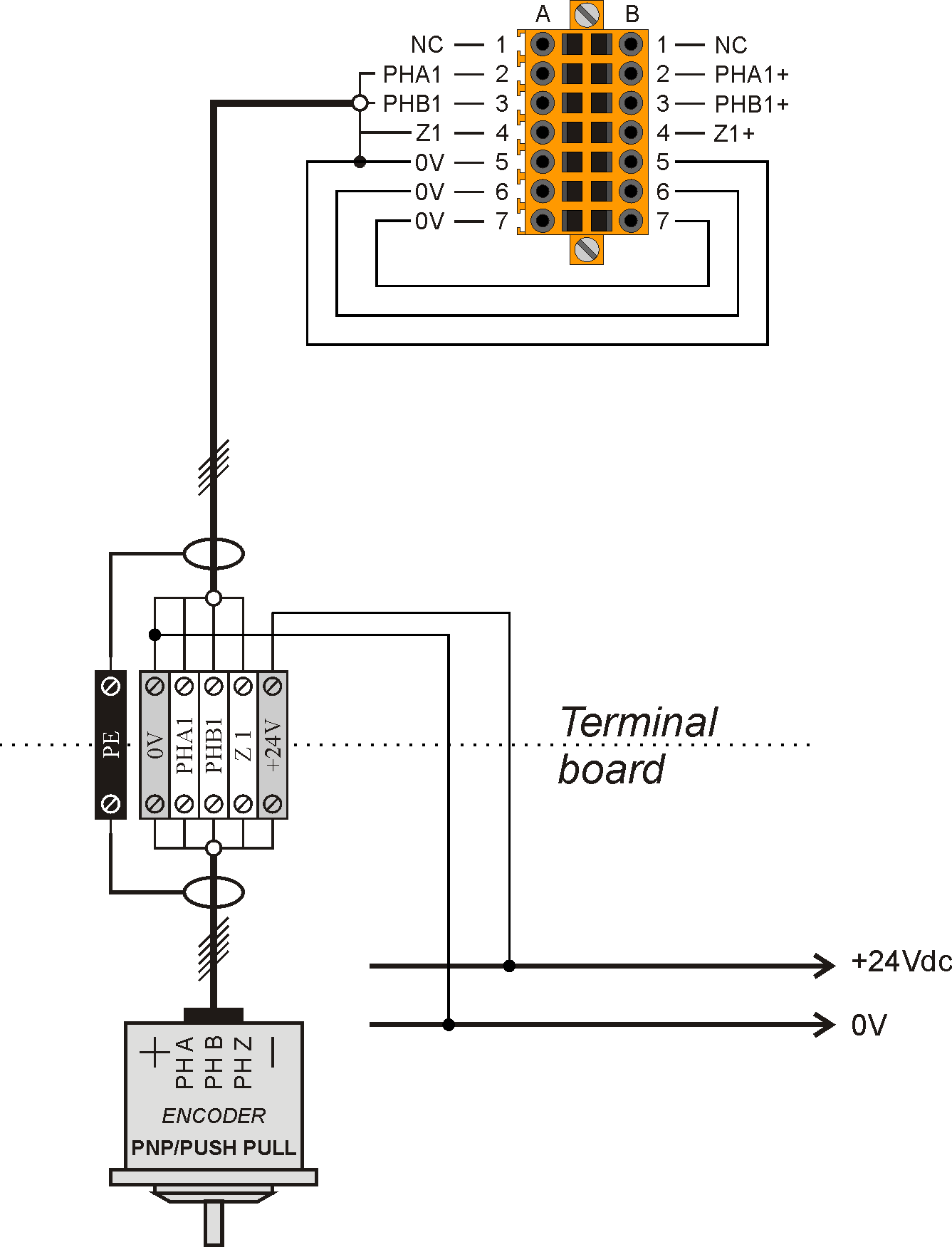
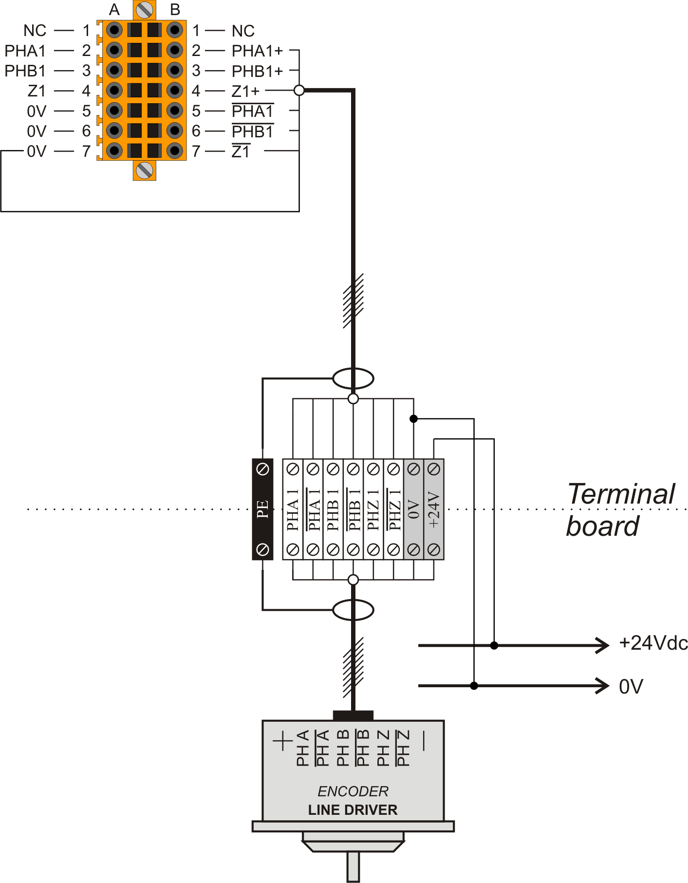
7.3 CN14, CN15, CN16, CN21 e CN22
Line-Driver encoder connection
PNP / Push Pull encoder connection