This is an old revision of the document!

Document release 8
RosettaCNC G-code language
All rights reserved on this manual. No part of this document can be copied or reproduced in any form without prior written authorisation. RosettaCNC Motion® does not insure or guarantee its contents and explicitly declines all liability related to the guarantee of its suitability for any purpose. The information in this document can be changed without notice. RosettaCNC Motion® shall not be held liable for any error or omission in this document. RosettaCNC Motion® is a registered trademark.
Information
| |
||||
| Document: | MDUROSETTACNCSOFTWAREGCODE | |||
|---|---|---|---|---|
| Description: | RosettaCNC G-code language | |||
| Link: | https://wiki.rosettacnc.com/doku.php/software/mdurosettacncsoftwaregcode | |||
| Release documento | Descrizione | Note | Data | |
| 01 | First release | / | 17/01/2018 | |
| 02 | Minor changes | / | 29/01/2019 | |
| 03 | Update for 1.6 version | / | 02/09/2019 | |
| 04 | Update for 1.7 version | / | 29/11/2019 | |
| 05 | Update for 1.7.6 version | / | 04/02/2020 | |
| 06 | Update for 1.7.7 version | / | 04/03/2020 | |
| 07 | Update for 1.8.5 version | / | 01/10/2020 | |
| 08 | Update for 1.9.1 version | / | 23/04/2021 | |
References
This manual explains the control software used by the RosettaCNC software.
All the implementation details refer to the software version: 1.9.1.
The actual control software version can be identified by open the “Help” menu → “About RosettaCNC”.
1. Supported G and M Codes
1.1 Supported G Codes
The following table describes supported G-Code commands.
The G-codes and M-codes called in the same line of a G-code file are executed accordingly to G Code Order of Execution.
In the following axes means one or more of X, Y, Z, A, B, C, along with a corresponding floating-point value for a specified axis.
| Gcode | Parameters | Command | Description |
|---|---|---|---|
| G0 | axes | Straight traverse | Traverse at maximum velocity. |
| G1 | axes F | Straight feed | Move at feed rate F. |
| G2 | axes F P IJK or R | Clockwise arc feed | Arc at feed rate F. |
| G3 | axes F P IJK or R | Counterclockwise arc feed | Arc at feed rate F. |
| G4 | P | Dwell | Pause for P seconds. |
| G9 | axes F | Exact Stop (non-modal) | Move at feed rate F and stop at the end. |
| G10 L1 | P axes | Set Tool Table Entry |
Update the tool table adding/updating the tool info with the tool offset set by the user. |
| G10 L10 | P axes | Set Tool Table, Calculated, Workpiece |
Update the tool table adding/updating the tool info with the tool offset calculated by the G-code interpreter. |
| G10 L2 | P axes | Coordinate System Origin Setting |
G10 L2 offsets the origin of the coordinate system specified by |
| G10 L20 | P axes | Coordinate Origin Setting Calculated | G10 L20 is similar to G10 L2 except that instead of setting the WCS origin offset, it calculates and sets the values that makes the current coordinates corresponds to the specified arguments. |
| G10 L100 | P<parameter> V<value> | Set the value of some special parameters | |
| G15 | Switch to Cartesian coordinates | ||
| G16 | Switch to polar coordinates | ||
| G17 | Select XY arc plane | ||
| G18 | Select XZ arc plane | ||
| G19 | Select YZ arc plane | ||
| G20 | Select inches mode | All G-code from this point on will be interpreted in inches | |
| G21 | Select mm mode | All G-code from this point on will be interpreted in millimetres | |
| G28 | axes | Go to G28 position | Optional axes specify an intermediate point |
| G28.1 | Set G28 position | Store the current machine position so that it will be used by G28 | |
| G30 | axes | Go to G30 position | Optional axes specify an intermediate point |
| G30.1 | Set G30 position | Store the current machine position so that it will be used by G30 | |
| G38.2 G38.3 G38.4 G38.5 | axes | Probing | |
| G40 | Disable Cutter Compensation | ||
| G41 | D I | Enable Cutter Compensation left of programmed path | |
| G41.1 | D L | Enable Dynamic Cutter Compensation left of programmed path | |
| G42 | D I | Enable Cutter Compensation right of programmed path | |
| G42.1 | D L | Enable Dynamic Cutter Compensation right of programmed path | |
| G43 | H | Enable Tool Length Compensation | H argument is optional, if it is not specified the current tool is used. |
| G43.1 | X Y Z | Enable Dynamic Tool Length Compensation | Tool compensation is enabled considering the specified offsets X, Y and Z. The arguments X,Y and Z are optional but at least one should be specified. |
| G43.2 | H | Apply additional Tool Length Offset | Add the offsets due to the tool specified with the H argument to the offsets already in use. |
| G43.4 | H | Enable RTCP feature | Enable Rotation tool center point control. (See 1. RTCP) |
| G43.7 | H <X> <Y> <Z> | Enable RTCP feature and override tool offsets using user defined arguments | |
| G49 | Cancel Tool Length Compensation and disable RTCP feature | ||
| G50 | Disable scaling | ||
| G51 | X Y Z and I J K or P | Enable scaling | |
| G52 | axes | Local Work Shift | The values entered are added to all work offsets |
| G53 | Select absolute coordinates | Non-Modal: Applies only to current block | |
| G54 | Select coord system 1 | G54 is typically used as the “normal” coordinate system and reflects the machine position | |
| G55 | Select coord system 2 | ||
| G56 | Select coord system 3 | ||
| G57 | Select coord system 4 | ||
| G58 | Select coord system 5 | ||
| G59 | Select coord system 6 | ||
| G59.1 | Select coord system 7 | ||
| G59.2 | Select coord system 8 | ||
| G59.3 | Select coord system 9 | ||
| G61 | Set exact path mode | ||
| G61.1 | Set exact stop mode | Motion will stop between each G-code block | |
| G64 | P Q | Continuous path mode | Results in minimum execution time allowing minimal trajectory deformation |
| G65 | P A B C … | Macro call | |
| G66 | P A B C … | Macro modal call | |
| G67 | Macro modal call cancel | ||
| G68 | X Y Z R | Coordinate System Rotation | |
| G68.2 | <X> <Y> <Z> I J K | 3D plane rotation (arcs not supported) | Rotate the reference plane in 3D so that G0,G1,G9 and cycles can be easily used on tilted planes. X ,Y,Z define the center of the rotation while I,J,K define the rotation around X, Y, Z. The order used to apply the rotation is always rotate around X, then Y, then Z. When G68.2 is active tool length compensation (G43, G43.1, …) can be enabled but tool radius compensation cannot be enabled. |
| G69 | Cancel Coordinate System Rotation | ||
| G73 | X Y Z R Q <L> | High Speed Peck Drilling Cycle Chip Break Drilling Cycle | |
| G80 | Cancel motion mode | ||
| G81 | X Y Z R L | Drilling Cycle | |
| G82 | X Y Z R L P | Drilling Cycle, Dwell | |
| G83 | X Y Z R L Q | Peck Drilling Cycle | |
| G85 | X Y Z R L | Boring Cycle, Feed Out | |
| G86 | X Y Z R L P | Boring Cycle, Spindle Stop, Rapid Move Out | |
| G88 | Boring Cycle, Spindle Stop, Manual Out | ||
| G89 | Boring Cycle, Dwell, Feed Out | ||
| G90 | Set absolute distance mode | ||
| G90.1 | Set absolute arc distance mode | Absolute distance mode for I, J & K offsets. When G90.1 is in effect I and J both must be specified with G2/3 for the XY plane or J and K for the XZ plane or it is an error | |
| G91 | Set incremental distance mode | ||
| G91.1 | Set incremental arc distance mode | Default arc mode | |
| G92 | axes | Set origin offsets | |
| G92.1 | Reset origin offsets | Reset parameters 5211 - 5219 to zero but G92 keeps its current state. Parameter 5210 remains 1 or 0 depending on its value before calling G92.1. | |
| G92.2 | Suspend origin offsets | ||
| G92.3 | Resume origin offsets | Set the G92 offsets to the values saved in parameters 5211 to 5219. | |
| G93 | Enable feed per inverse of time | When this G code is processed the target feed is set to 60 (seconds) divided by the F<target feed> value. |
|
| G94 | Enable feed per minute | When this G code is processed the target feed is set to 0 and should be specified again using F<target feed>. |
|
| G98 | Canned cycle return mode | Initial Level Return In Canned Cycles set to initial Z | |
| G99 | Canned cycle return mode | Initial Level Return In Canned Cycles set to R parameter | |
| G100 | P A B C … | Internal PLC function Call | |
| G101 | P | Set the axes to be interpolated | Request the axes specified by the P parameter to be interpolated. The P parameter is a bitmask where bit 1 represents X axis, bit 2 Y axis, …. |
| G102 | P | Homing request | Request the axes specified by the P parameter to be homed. The P parameter is a bitmask where bit 1 represents X axis, bit 2 Y axis, …. |
| G103 | V | Set traverse rate | The maximum speed used for G0 motion. Units are mm/min. Zero means use the maximum value allowed by the axes involved in the movement. |
| G104 | A D <J> | Set interpolated motion dynamics | Set the maximum acceleration and deceleration along the trajectory during interpolated motion. When A/D is set to 0 the maximum acceleration/deceleration allowed by the axes involved in the movement is used. Units are mm/s^2 if G21 is active and inches/s^2 if G20 is active. Example: G104 A100 D50 to set a maximum acceleration of 100 mm/s^2 and a maximum deceleration of 50 mm/s^2. J is optional and can be used to set the jerk in % from 0.0 to 100.0. 0 Means accelerate with a slower ramp, 100% means accelerate immediately. |
| G200÷G499 | A B C … | User defined G codes | User defined G codes require a user edited G-code file in macros folder with the G-code name (eg: g212.ngc). |
1.2 Supported M Codes
| Mcode | Parameters | Command | Description |
|---|---|---|---|
| M0 | Program Stop | Current implementation place the CNC in PAUSE state. | |
| M1 | Program Optional Stop | Current implementation place the CNC in PAUSE state if the optional stop input is on. | |
| M2 | Program End | End a G-code program and reset the machine state: switch off I/O, mist, flood and spindle. | |
| M3 | Start spindle clock wise | ||
| M4 | Start spindle counter clock wise | ||
| M5 | Stop spindle turning | ||
| M6 | Tool change | See also User Tool Change Subprogram | |
| M7 | Mist On | ||
| M8 | Flood On | ||
| M9 | Mist and Flood Off | ||
| M17 | Turn On Torch Height Control (THC) | ||
| M18 | Turn Off Torch Height Control (THC) | ||
| M30 | Pallet shuttle and program end | If the correspondent settings is enabled the user G-code macro pallet_shuttle.ngc can be called. | |
| M47 | Restart program execution | ||
| M48 | Enable the feed rate and spindle speed override controls | ||
| M49 | Disable the feed rate and spindle speed override controls | ||
| M50 | <P> | Enable/Disable the feed rate override control. |
|
| M51 | <P> | Enable/Disable the spindle speed override control. | Usage: M51 P1 (or M51) enable spindle speed override control and M51 P0 disable it. The P parameter is optional. |
| M60 | Pallet shuttle | If the correspondent settings is enabled the user G-code macro pallet_shuttle.ngc can be called. | |
| M61 | Q | Set the current tool without performing a tool change. | Could be called from user G-code defined tool change macro, see also User Tool Change Subprogram. |
| M62 | P | Turn out ON | |
| M63 | P | Turn out OFF | |
| M66 | P L Q | Wait input | Parameters:
Notes:
|
| M67 | P | Read analog input | Work the same way of M66 but is used to handle analog inputs |
| M68 | P Q | Set analog output | Used instead of M62/M63 for analog outputs. Q argument is used to set the desired analog output value in percentage. |
| M98 | P L | Call Subroutine | Note: a named external subroutine can be called |
| M99 | Return from Subroutine | ||
| M102 | End Program without reset | End a program but does not perform an automatic reset switching off mist, flood, spindle status, … | |
| M106 | Execute PLC internal tool change procedure | This M code is intended to be called by the user from the file named tool_change.ngc. This code inform the PLC to start the internal tool change procedure that can perform a few automatic actions not described by the procedure described using the G-code. See also User Tool Change Subprogram. | |
| M107 | Inform the PLC that the tool change procedure written in the User Tool Change Subprogram has started. | ||
| M108 | Inform the PLC that the tool change procedure written in the User Tool Change Subprogram has ended. | ||
| M109 | P Q D | Show user message | |
| M120 | P Q D | Show user media | |
| M166 | P | Read digital input group | The parameter P identifies the group. This M code updates the parameters #5740- #5759 |
| M167 | P | Read input group | The parameter P identifies the group. This M code updates the parameters #5740- #5759 |
| M200÷M299 | A B C … | User defined M codes | User defined M codes require a user edited G-code file with the macro name and .ngc extension to be place in the directory <%appdata%/RosettaCNC-1>/machines/<machine_name>/macros (eg: m210.ngc). |
1.3 Other Codes
Simple G-code commands are used for setting the speed, feed, and tool parameters.
“F” for “Feed”
The F command sets the feed rate; the machine operates at the set feed rate when G1 is used, and subsequent G1 commands will execute at the set F value.
If the feed rate (F) is not set once before the first G1 call, either an error will occur or the machine will operate at its “default” feed rate.
An example of a valid F command: G1 F1500 X100 Y100
To see how RosettaCNC handled the feed rate when for single rotary axis moves or for mixed moves please check Feed Management
“S” for “Spindle Speed”
The S command sets the spindle speed, typically in revolutions per minute (RPM). An example of a valid S command:
S10000
“T” for “Tool”
The T command is used to set the id of the tool to be loaded with the M6 command.
The typical syntax to load the tool with id 1 would be:
M6 T1
Notes
- Setting the Tool Change Type option to Macro in the Board Settings the user can customize the tool change procedure.
If the option is enabled theM06command will look into the machine macros folder and execute the G-code file namedtool_change.ngc.
In this file the user can specify any supported G-code command to perform the tool change procedure as required by the specific machine.
To see a reference implementation of the filetool_change.ngcplease take a look to User Tool Change Subprogram.
1.4 G-Code Comments
The following syntaxes are supported:
(…): simple comment between brackets;: simple comment till the end of the line started with a semi column
1.5 Block delete
Block Delete, also called Optional Skip, determines what happens when a line of code has a forward slash mark (/).
In RosettaCNC integrated G-Code editor there is a dedicated icon to enable/disable this feature.
When the feature is enabled and a line of G-Code begins with a forward slash the line is ignored and the execution skips to the next line of code.
1.6 Go to predefined positions
1.6.1 G28 and G28.1
G28 uses the values stored in parameters 5161-5166 as the X Y Z A B C final point to move to.
The parameter values are absolute machine coordinates
- G28 - makes a rapid move from the current position to the absolute position of the values in parameters 5161-5166. Since the position stored in the parameters 5161-5166 is considered absolute the tool offset enabled with G43 influences the position. Example: #5163 = 0, tool_offset_z = 50 → target_position = #5163 - tool_offset_z = -50.
- G28 axes - makes a rapid move to the position specified by axes including any offsets, then will make a rapid move to the absolute position of the values in parameters 5161-5166 for axes specified.
Any axis not specified will not move. - G28.1 - stores the current absolute position into parameters 5161-5166. Note: G28.1 does not take any argument, the current absolute machine position is stored.
Examples
G28 (rapid move to the values specified into the stored parameters, moving all axes)
G28 Z10.0 (rapid move to Z10.0 then to location specified in the G28 stored parameters, moving only Z)
G28 G91 Z0 (rapid relative move to relative Z0.0 then to location specified in the G28 stored parameters, moving only Z)
The last example skip the intermediate position, since the movement is relative and with a displacement of 0.
It is usually used to ensure that only axis Z will move to the homing position specified in G28 parameters.
1.6.2 G30 and G30.1
G30 uses the values stored in parameters 5181-5186 as the X Y Z A B C final point to move to.
The parameter values are absolute machine coordinates
- G30 - makes a rapid move from the current position to the absolute position of the values in parameters 5181-5186.
- G30 axes - makes a rapid move to the position specified by axes including any offsets, then will make a rapid move to the absolute position of the values in parameters 5181-5186 for axes specified.
Any axis not specified will not move. - G30.1 - stores the current absolute position into parameters 5181-5186. Note: G30.1 does not take any argument, the current absolute machine position is stored.
1.6.2.1 Examples

( © 2018 by RosettaCNC Motion                                 )
( file name: g28_example.ngc                                  )

G17 G21 G40 G49 G50 G54 G69 G90

#5161=20    ( G28 X )
#5162=40    ( G28 Y )
#5163=20    ( G28 Z )

G52 X20 Y20
G28 G91 Z0
M98 P1000
; Since Z axis is specified only axis Z will be moved to the
; position stored in parameter 5163.
; Since the intermediate point Z0 is specified with G91 the
; intermediate point position will be skipped.
G28 G91 Z0
G90

G52 X50 Y50
M98 P1000
; If no axis is specified with the G28 the position stored in
; the parameters 5161-5166 is used.
G28

M2

( Square )
O1000
    G90
    G0 X0 Y0 Z0
    G1 X10
    Y10
    X0
    Y0
M99
1.7 G Code Order of Execution
The order of execution of items on a line is defined not by the position of each item on the line, but by the following list:
- the entire line is skipped if it starts with a forward slash
/and the block delete toggle is active - comments started with
(or; - if N is the first letter of a line the following number is interpreted as line number
- when a subroutine declaration is found (example
O1001) the remaining part of the line is allowed only to be a comment. - control flow statements like
WHILE,IF - set feed rate mode
G93,G94 - set feed rate
F - set spindle speed
S - I/O handling:
M62,M63,M66 - change tool:
M6if user tool change macro is disabled,M61,M106 - spindle on or off:
M3,M4,M5 - coolant on or off:
M7,M8,M9,M17,M18 M48,M49M109,M120- dwell
G4 - set active plane:
G17,G18,G19 - set length units:
G20,G21 - cutter radius compensation on or off:
G40,G41,G42 - cutter length compensation on or off:
G43,G49 - coordinate system selection:
G54,G55,G56,G57,G58,G59,G59.1,G59.2,G59.3 - set path control mode:
G61,G61.1,G64 - set distance mode:
G90,G91 - set arc mode:
G90.1,G91.1 - set retract mode:
G98,G99 - non modal G-codes:
G10,G28,G28.1,G30,G30.1,G52,G92,G92.1,G92.2,G92.3 - scaling:
G50,G51 - rotation:
G68,G69 - motion:
G0,G1,G2,G3,G9,G76,G80 - stop:
M0,M1,M2,M30,M47 - control flow statements like
GOTO - subroutines and macros:
M98,M6only if user tool change macro is enabled
Some codes require to be the only G/M codes in the line, they are: G65, G100, user defined m codes and user defined g codes
1.8 Arcs & Helices
A circular or helical arc is specified using either G2 (clockwise arc) or G3 (counterclockwise arc) at the current feed rate.
The direction (CW, CCW) is as viewed from the positive end of the axis about which the circular motion occurs.
The plane used for the circle or helix must be one between XY, YZ, or XZ.
The plane is selected with G17 (XY-plane), G18 (XZ-plane), or G19 (YZ-plane).
The P word can be used to specify the number of full turns plus the programmed arc.
The P word must be an integer. If P is unspecified, the behaviour is as if P1 was given: that is, only one full or partial turn will result.
For each P increment above 1 an extra full circle is added to the programmed arc.
Multi turn helical arcs are supported and give motion useful for milling holes or threads.
Note If a line of code makes an arc and includes rotary axis motion, the rotary axes turn so that the rotary motion starts and finishes when the XYZ motion starts and finishes.
1.8.1 Syntax

1.8.2 Center Format Arcs
Center format arcs are more accurate than radius format arcs and are the preferred format to use.
The end point of the arc along with the offset to the center of the arc from the current location are used to program arcs that are less than a full circle.
If the end point of the arc is the same as the current location a full circe is generated.
G2 or G3 axes offsets P
G2 or G3 offsets P can be used for full circles
Incremental Arc Distance Mode
This is the default Distance Mode for the arc center offsets (I, J, K) that are relative distances from the start location of the arc.
One or more axis words and one or more offsets must be programmed for an arc that is less than 360 degrees.
This mode is enabled with G91.1.

Absolute Arc Distance Mode
Arc center offsets (I, J, K) are relative distances from the current origin of the axes.
One or more axis words and both offsets must be programmed for arcs less than 360 degrees.
This mode is enabled with G90.1.
1.8.3 Radius Format Arcs
G2 or G3 axes R- P

1.8.4 Examples
1.8.5 Center format arcs incremental mode

1.8.6 Full circles and helices

( © 2018 by RosettaCNC Motion             )
( file name: full_circles_and_helices.ngc )

G21 G40 G49 G90 G54 G50 G69
M3 F2000
G0 X0 Y0 Z0

G17 ; XY plane
G2 I0 J25
G18 ; XZ plane
G2 I0 K25
G19 ; YZ plane
G2 J0 K25

T3 M6
G52 X100
G0 X0 Y0 Z0
; helixes
G17
G2 I0 J25 Z100 P2
G0 X0 Y0 Z0
G18 ; XZ plane
G2 I0 K25 Y100 P2
G0 X0 Y0 Z0
G19 ; YZ plane
G2 J0 K25 X100 P2

M2
2. G-Code variables
Rosetta CNC supports Macro programming (following Fanuc Macro B style).
Your G-Code programs or sub-programs can include a few non-G-Code commands that use variables, arithmetic, logic statements, and looping are available.
Rosetta CNC supports 7000 variables that can be accessed from the G-code. These variables are divided into 5 groups as described in the following table.
| Variable Number | Type of Variable | Function |
|---|---|---|
| #0 | Null | #0 is read-only and its value is always “null” that means “no value”. |
| #1-#33 | Local Variables | Local variables are used to pass arguments to macros and as temporary scratch storage. |
| #100-#499 | Input Variables | The value of these variables can be set by the user through the GUI and the value in the table will never be changed by the controller. |
| #500-#3999 | Program Variables | The value of these variables can be read/write by G-code programs and are initialized with #0 before executing a program. |
| #4000-#4999 | Shared Variables | The value of these variables is shared between the GUI interface and the controller. The result is that if during a program one of these variables is changed the user can see the updated final value in the table. |
| #5000-#5999 | System Variables | Updated run time by the compiler |
| #6000-#6999 | Protected Variables | Variables that can be modified by the user only before compilation and that are password protected. A G-code program can only read these variables and not write them. |
2.1 System variables description
| System Variable | Meaning |
|---|---|
| Current Position Variables | Current Position variables Meaning |
| 5001-5006 | Current TCP position X – C See position information table |
| 5081-5086 | Current TCP position when restarting X - C |
| 5091-5093 | Last stop position X, Y, Z [inches or mm depending on parameter 5106] |
| 5094-5096 | Last stop position A, B, C |
| Active G-codes Variables | Active G-codes Variables Meaning |
| 5100 | Sequence number of lines executed |
| 5101 | Group 01: G0, G1, G2, G3, G38.X, G73, G80, G81, G82, G83, G84, G85, G86, G87, G88, G89 |
| 5102 | Group 02: G17, G18, G19 |
| 5103 | Group 03: G90, G91 |
| 5104 | Group 04: G90.1, G91.1 |
| 5105 | Group 05: G93, G94 |
| 5106 | Group 06: G20, G21 |
| 5107 | Group 07: G40, G41, G41.1, G42, G42.1 |
| 5108 | Group 08: G43, G43.1, G43.2, G43.4, G43.7, G49 |
| 5110 | Group 10: G98, G99 |
| 5111 | Group 11: G50, G51 |
| 5112 | Group 12: G54, G55, G56, G57, G58, G59, G59.1, G59.2, G59.3 |
| 5113 | Group 13: G61, G61.1, G64 |
| 5116 | Group 16: G68, G69 |
| 5117 | Group 17: G15, G16 |
| Other codes | Other codes meaning |
| 5120 | Interpolated-Grouprd axes mask. Value is a bitmask where bit 1 represents X axis, bit 2 Y axis, .. |
| 5127 | Active jerk [%] |
| 5128 | Active max acceleration [mm/s^2 or inches/s^2] (0 means use the maximum acceleration) |
| 5129 | Active max deceleration [mm/s^2 or inches/s^2] (0 means use the maximum deceleration) |
| 5130 | Active feed rate (F) |
| 5131 | Active spindle speed (S) |
| 5132 | Selected tool (T) |
| 5133 | Selected slot |
| 5134 | Current tool |
| 5135 | Current slot |
| 5136 | Active feed rate override mode, P argument of M50 |
| 5137 | Active spindle speed override mode, P argument of M51 |
| 5138 | Active traverse rate: target speed during G0 commands. 0 means use the maximum possible speed. [mm/s^2 or inches/s^2] |
| 5139 | Active user tool change procedure: 1 means procedure active (Between M107 and M108) |
| 5140 | Tolerance set with G64 P |
| 5141 | Points removal threshold set with G64 Q |
| 5148 | While a modal macro is active it stores how many times a modal macro (G66) has been called. |
| 5149 | Executing sub-program. Flag set to 1 while G-code is executing a sub-program called from the main program. |
| Active M-codes | Active M-codes meaning |
| 5150 | M0, M2, M30, M47, M60 |
| 5151 | M3, M4, M5 |
| 5152 | M6, M106 |
| 5153 | M7, M9 |
| 5154 | M8, M9 |
| 5155 | M48, M49, M51 |
| 5156 | M48, M49, M51 |
| G28, G28.1 Variables | G28, G28.1 Variables Meaning |
| 5161 | G28.1 position X |
| 5162 | G28.1 position Y |
| 5163 | G28.1 position Z |
| 5164 | G28.1 position A |
| 5165 | G28.1 position B |
| 5166 | G28.1 position C |
| G30, G30.1 Variables | G30, G30.1 Variables Meaning |
| 5181 | G30.1 position X |
| 5182 | G30.1 position Y |
| 5183 | G30.1 position Z |
| 5184 | G30.1 position A |
| 5185 | G30.1 position B |
| 5186 | G30.1 position C |
| WCS Offsets Variables | WCS Offsets Variables Meaning |
| 5201 - 5206 | G52 offset X - C |
| 5210 | G92 enabled (0 ÷ 1) |
| 5211 - 5216 | G92 offset X - C |
| WCS Variables | WCS Variables Meaning |
| 5220 | Coord. System number |
| 5221 - 5226 | Coord. System 1 X – C |
| 5241 - 5246 | Coord. System 2 X – C |
| 5261 - 5266 | Coord. System 3 X – C |
| 5281 - 5286 | Coord. System 4 X – C |
| 5301 - 5306 | Coord. System 5 X – C |
| 5321 - 5326 | Coord. System 6 X – C |
| 5341 - 5346 | Coord. System 7 X – C |
| 5361 - 5366 | Coord. System 8 X – C |
| 5381 - 5386 | Coord. System 9 X – C |
| Tool Variables | Tool Variables Meaning |
| 5400 | Current tool id |
| 5401 | Current tool offset X |
| 5402 | Current tool offset Y |
| 5403 | Current tool offset Z / Current tool length |
| 5410 | Current tool diameter |
| 5411 | Current tool type |
| 5412 | Current tool parameter 1 |
| 5413 | Current tool parameter 2 |
| 5414 | Current tool parameter 3 |
| 5420 | Tool compensation offset X (Set using G43, G43.1, G43.2, G43.4, G43.7, G49) |
| 5421 | Tool compensation offset Y (Set using G43, G43.1, G43.2, G43.4, G43.7, G49) |
| 5422 | Tool compensation offset Z (Set using G43, G43.1, G43.2, G43.4, G43.7, G49) |
| 5423 | Tool compensation offset A (Set using G43, G43.1, G43.2, G43.4, G43.7, G49) |
| 5424 | Tool compensation offset B (Set using G43, G43.1, G43.2, G43.4, G43.7, G49) |
| 5425 | Tool compensation offset C (Set using G43, G43.1, G43.2, G43.4, G43.7, G49) |
| 5426 | The id of the tool used for tool compensation, both normal(G43, G43.1, G43.2) and RTCP (G43.4, G43.7) |
| 5427 | The type of the tool used for tool compensation |
| Scaling & Rotation Variables | Scaling and Rotation Variables Meaning |
| 5501 | G51 scaling factor X |
| 5502 | G51 scaling factor Y |
| 5503 | G51 scaling factor Z |
| 5504 | G51 offset X |
| 5505 | G51 offset Y |
| 5506 | G51 offset Z |
| 5510 | G68 rotation plane |
| 5511 | G68 rotation XY |
| 5512 | G68 rotation XZ |
| 5513 | G68 rotation YZ |
| 5514 | G68 offset X |
| 5515 | G68 offset Y |
| 5516 | G68 offset Z |
| Runtime External Variables | Runtime External Variables Meaning |
| 5700 | Probe state at the end of a G38.X. Values: 1 probing procedure succeeded, -1 failed: sensor not tripped before reaching the target position, -2 failed: sensor already tripped |
| 5701 - 5706 | Probed position loaded at the end of a G38.X with respect to the active WCS See position information table |
| 5711 - 5716 | Probed position X - C loaded at the end of a G38.X with respect to machine coordinates See position information table |
| 5720 | Return value for M66 |
| 5721 | Return value for M109 and M120 |
| 5722 | Status of the last M66 (0 → Success, 1 → Failure) |
| 5730-5734 | User input values from M109 or M120 |
| 5735-5739 | User input values from M109 or M120 |
| 5740-5744 | Input values for M166 and M167 |
| 5745-5749 | Input values for M166 and M167 |
| 5750-5754 | Input values for M166 and M167 |
| 5755-5759 | Input values for M166 and M167 |
| Parameters Related Variables | Parameters Related Variables (Set using G10 L100 P<param> V<value>) |
| 5800 | The motion mode used when G66 is enabled (0 → G0; 1 → G1) |
| 5801 | Rotary axis modulus used for the rollover |
| 5802 | Axis A rotary mode (see Rotary axis options) |
| 5803 | Axis B rotary mode (see Rotary axis options) |
| 5804 | Axis C rotary mode (see Rotary axis options) |
| Restart related position variables | Meaning |
| 5091-5096 | Last stop positions. X,Y and Z in inches or mm depending on parameter 5106 and A,B,C in deg |
2.2 Named variables
Named variables work like normal numbered variables but are easier to read.
Syntax:
- Named variables must be enclosed between
<>marks. - All variable names are converted to lower case and have spaces and tabs removed, so
<named variable>and< Nam ed Var i Able>represent to the very same variable. - A named variable starts to exist when it is assigned a value for the first time.
- You can check if a named parameter already exists with the unary operation
EXISTS[arg].
Example:IF [EXISTS[#<_args.c>] EQ 0] THEN GOTO 10 - When a macro is called the passed arguments can be read using the correspondent named variable preceded by
_args. Example: to get the value of thexargument you can use#<_args.x>.
2.2.1 Global and local scopes
A named parameter whose name starts with _ is local to the scope in which it is created. A local named variable vanishes when its scope is left. Indeed, when a local variable is declared in a subroutine and the subroutine returns, the variable is deleted and cannot be referred to anymore.
#<named_variable>is a global named variable.#<_named_variable>is a local named variable.
2.2.2 Indexing support
Both global and local variables support indexing with a syntax similar to C style arrays.
Every expression between brackets ([,]) in a variable name is evaluated by the G-code interpreter.
Examples:
#<named_variable[#<index>]>is evaluated as#<named_variable[10]>if#<index>has been previously set to 10.#<named_variable[#<index1> + 1][#<index2>]>is evaluated depending on the variables#<index1>and#<index2>
2.2.3 Pre-defined Named Parameters
The G-Code compiler has a pre-defined set of read-only named parameters which can be useful in the Program/Macro/MDI editing.
There are nine groups:
#<sys.xxx>which contains info about the system.
#<math.xxx>which contains usefull math constants.
#<cnc.xxx>which contains some of CNC setup settings.
#<compile.xxx>which contains the compile enums.
#<kinematics.xxx>which contains the kinematics enums.
#<axis.xxx>which contains the axis enums.
#<tool.xxx>which contains the tool enums.
#<probe.xxx>which contains the probe enums.
#<wait_input>which contains theM66wait enums.
#<pick_place.xxx>which contains the ATCM enums.
| Named Variable | Description |
|---|---|
#<sys.version.major> | The major version of CNC Core System (e.g. returns 0 of 0.3.7.167 version) |
#<sys.version.minor> | The minor version of CNC Core System (e.g. returns 3 of 0.3.7.167 version) |
#<sys.version.release> | The release version of CNC Core System (e.g. returns 7 of 0.3.7.167 version) |
#<sys.version.build> | The build version of CNC Core System (e.g. returns 167 of 0.3.7.167 version) |
#<sys.customer_id> | The customer ID (usually values 0) |
#<sys.interface_level> | Interface Level (for Control Software 1.9.2 will be 9) |
#<sys.ui.units_mode> | User Interface units mode:20 = Imperial (in)21 = Metric (mm) |
| |
|
| |
|
#<math.max> | Max value (1.7e+308) |
#<math.min> | Min value (5e-324) |
#<math.nan> | NaN value (-NAN) |
#<math.infinity> | Infinity value (+INF) |
#<math.neg_infinity> | Negative infinity value (-NAN) |
#<math.e> | Euler's number (2.7182818284590452354) |
#<math.pi> | Archimedes constant (3.14159274101257324218) |
#<math.ln_2> | Natural Log of 2 (0.69314718055994530942) |
#<math.ln_10> | Natural Log of 10 (2.30258509299404568402) |
#<math.ln_pi> | Natural Log of pi (1.14472988584940017414) |
#<math.to_mm> | Factor to convert inches to mm (25.4) |
#<math.to_in> | Factor to convert mm to inches (1/25.4) |
#<math.to_rad> | Factor to convert deg to rad (PI/180) |
#<math.to_deg> | Factor to convert rad to deg (180/PI) |
| |
|
| |
|
#<cnc.compile.mode> | Describes the modality of G-Code compilation (see #<compile.xxx> section for a detailed description) |
#<cnc.compile.line> | Contains the staring G-Code line for the compile modes #<compile.mode_program_from_line> and #<compile.mode_program_for_resume_from_line> |
| |
|
| |
|
#<cnc.machine_type> | Machine Type: 0 = Mill |
#<cnc.kinematics_model> | Describes the Kinematics Model in use (see #<kinematics.xxx> section for a detailed description) |
| |
|
#<cnc.x.type> | X Axis Type (see #<axis.type.xxx> section for a detailed description) |
#<cnc.x.max_vel> | X Axis Max Velocity [mm/min] |
#<cnc.x.acc> | X Axis Acceleration [mm/s²] |
#<cnc.x.min_lim> | X Axis Min Limit [mm] |
#<cnc.x.max_lim> | X Axis Max Limit [mm] |
| |
|
#<cnc.y.type> | Y Axis Type (see #<axis.type.xxx> section for a detailed description) |
#<cnc.y.max_vel> | Y Axis Max Velocity [mm/min] |
#<cnc.y.acc> | Y Axis Acceleration [mm/s²] |
#<cnc.y.min_lim> | Y Axis Min Limit [mm] |
#<cnc.y.max_lim> | Y Axis Max Limit [mm] |
| |
|
#<cnc.z.type> | Z Axis Type (see #<axis.type.xxx> section for a detailed description) |
#<cnc.z.max_vel> | Z Axis Max Velocity [mm/min] |
#<cnc.z.acc> | Z Axis Acceleration [mm/s²] |
#<cnc.z.min_lim> | Z Axis Min Limit [mm] |
#<cnc.z.max_lim> | Z Axis Max Limit [mm] |
| |
|
#<cnc.a.type> | A Axis Type (see #<axis.type.xxx> section for a detailed description) |
#<cnc.a.max_vel> | A Axis Max Velocity [mm/min] |
#<cnc.a.acc> | A Axis Acceleration [mm/s²] |
#<cnc.a.min_lim> | A Axis Min Limit [mm] |
#<cnc.a.max_lim> | A Axis Max Limit [mm] |
#<cnc.a.motion_mode> | A Axis Motion Mode: 0 = Continuous 1 = Indexing |
#<cnc.a.convention> | A Axis Convention: 0 = Normal 1 = Inverse |
#<cnc.a.wrapped_rotary> | A Axis Wrapped Rotary State: 0 = Disabled 1 = Enabled |
#<cnc.a.parallel_to> | A Axis Parallet to: 0 = X 1 = Y 2 = Z |
#<cnc.a.origin_mode> | A Axis Origin Mode: 0 = Custom 1 = WCS 1 - G542 = WCS 2 - G553 = WCS 3 - G564 = WCS 4 - G575 = WCS 5 - G586 = WCS 6 - G597 = WCS 7 - G59.18 = WCS 8 - G59.29 = WCS 9 - G59.3 |
#<cnc.a.origin_x> | A Axis Origin X [mm] |
#<cnc.a.origin_y> | A Axis Origin Y [mm] |
#<cnc.a.origin_z> | A Axis Origin Z [mm] |
| |
|
#<cnc.b.type> | B Axis Type (see #<axis.type.xxx> section for a detailed description) |
#<cnc.b.max_vel> | B Axis Max Velocity [mm/min] |
#<cnc.b.acc> | B Axis Acceleration [mm/s²] |
#<cnc.b.min_lim> | B Axis Min Limit [mm] |
#<cnc.b.max_lim> | B Axis Max Limit [mm] |
#<cnc.b.motion_mode> | B Axis Motion Mode: 0 = Continuous 1 = Indexing |
#<cnc.b.convention> | B Axis Convention: 0 = Normal 1 = Inverse |
#<cnc.b.wrapped_rotary> | B Axis Wrapped Rotary State: 0 = Disabled 1 = Enabled |
#<cnc.b.parallel_to> | B Axis Parallet to: 0 = X 1 = Y 2 = Z |
#<cnc.b.origin_mode> | B Axis Origin Mode: 0 = Custom 1 = WCS 1 - G542 = WCS 2 - G553 = WCS 3 - G564 = WCS 4 - G575 = WCS 5 - G586 = WCS 6 - G597 = WCS 7 - G59.18 = WCS 8 - G59.29 = WCS 9 - G59.3 |
#<cnc.b.origin_x> | B Axis Origin X [mm] |
#<cnc.b.origin_y> | B Axis Origin Y [mm] |
#<cnc.b.origin_z> | B Axis Origin Z [mm] |
| |
|
#<cnc.c.type> | C Axis Type (see #<axis.type.xxx> section for a detailed description) |
#<cnc.c.max_vel> | C Axis Max Velocity [mm/min] |
#<cnc.c.acc> | C Axis Acceleration [mm/s²] |
#<cnc.c.min_lim> | C Axis Min Limit [mm] |
#<cnc.c.max_lim> | C Axis Max Limit [mm] |
#<cnc.c.motion_mode> | C Axis Motion Mode: 0 = Continuous 1 = Indexing |
#<cnc.c.convention> | C Axis Convention: 0 = Normal 1 = Inverse |
#<cnc.c.wrapped_rotary> | C Axis Wrapped Rotary State: 0 = Disabled 1 = Enabled |
#<cnc.c.parallel_to> | C Axis Parallet to: 0 = X 1 = Y 2 = Z |
#<cnc.c.origin_mode> | C Axis Origin Mode: 0 = Custom 1 = WCS 1 - G542 = WCS 2 - G553 = WCS 3 - G564 = WCS 4 - G575 = WCS 5 - G586 = WCS 6 - G597 = WCS 7 - G59.18 = WCS 8 - G59.29 = WCS 9 - G59.3 |
#<cnc.c.origin_x> | C Axis Origin X [mm] |
#<cnc.c.origin_y> | C Axis Origin Y [mm] |
#<cnc.c.origin_z> | C Axis Origin Z [mm] |
| |
|
#<cnc.u.type> | U Axis Type (see #<axis.type.xxx> section for a detailed description) |
#<cnc.u.max_vel> | U Axis Max Velocity [mm/min] |
#<cnc.u.acc> | U Axis Acceleration [mm/s²] |
#<cnc.u.min_lim> | U Axis Min Limit [mm] |
#<cnc.u.max_lim> | U Axis Max Limit [mm] |
| |
|
#<cnc.v.type> | V Axis Type (see #<axis.type.xxx> section for a detailed description) |
#<cnc.v.max_vel> | V Axis Max Velocity [mm/min] |
#<cnc.v.acc> | V Axis Acceleration [mm/s²] |
#<cnc.v.min_lim> | V Axis Min Limit [mm] |
#<cnc.v.max_lim> | V Axis Max Limit [mm] |
| |
|
#<cnc.w.type> | W Axis Type (see #<axis.type.xxx> section for a detailed description) |
#<cnc.w.max_vel> | W Axis Max Velocity [mm/min] |
#<cnc.w.acc> | W Axis Acceleration [mm/s²] |
#<cnc.w.min_lim> | W Axis Min Limit [mm] |
#<cnc.w.max_lim> | W Axis Max Limit [mm] |
| |
|
| |
|
#<cnc.spindle.max_speed> | Spindle Max Speed [rpm] |
| |
|
#<cnc.rotary_table.d_x> | Rotary Table D:X [mm] |
#<cnc.rotary_table.d_y> | Rotary Table D:Y [mm] |
#<cnc.rotary_table.d_z> | Rotary Table D:Z [mm] |
| |
|
#<cnc.tilting_spindle.h_x> | Tilting Spindle H:X [mm] |
#<cnc.tilting_spindle.h_y> | Tilting Spindle H:Y [mm] |
#<cnc.tilting_spindle.h_z> | Tilting Spindle H:Z [mm] |
#<cnc.tilting_spindle.j_x> | Tilting Spindle J:X [mm] |
#<cnc.tilting_spindle.j_y> | Tilting Spindle J:Y [mm] |
#<cnc.tilting_spindle.j_z> | Tilting Spindle J:Z [mm] |
| |
|
| |
|
#<compile.mode_mdi> | The G-Code compiler is compiling an MDI command |
#<compile.mode_macro> | The G-Code compiler is compiling a Macro (from User Input or a Top Toolbar Button) |
#<compile.mode_program> | The G-Code compiler is compiling the main Program |
#<compile.mode_program_from_line> | The G-Code compiler is compiling the main Program starting from a specified line of code |
#<compile.mode_program_for_resume> | The G-Code compiler is compiling the main Program for a RESUME command after a STOP command |
#<compile.mode_program_for_resume_from_line> | The G-Code compiler is compiling the main Program for a RESUME from specific line after a STOP command |
#<compile.mode_program_for_analysis'> | The G-Code compiler is compiling the main Program for analysis |
| |
|
| |
|
#<kinematics.model.trivial> | Kinematics Model: Trivial (0) |
#<kinematics.model.independent_rot_axes> | Kinematics Model: Independent Rotational Axes (1) |
#<kinematics.model.rotary_table_ac> | Kinematics Model: Rotary Table AC (2) |
#<kinematics.model.rotary_table_bc> | Kinematics Model: Rotary Table BC (3) |
#<kinematics.model.tilting_spindle_ca> | Kinematics Model: Tilting Spindle CA (4) |
#<kinematics.model.tilting_spindle_ab> | Kinematics Model: Tilting Spindle AB (5) |
| |
|
| |
|
#<axis.type.disabled> | Axis Type: Disabled (0) |
#<axis.type.linear> | Axis Type: Linear (1) |
#<axis.type.rotary_free> | Axis Type: Rotary Free (2) |
#<axis.type.rotary_head> | Axis Type: Rotary Head (3) |
#<axis.type.rotary_table> | Axis Type: Rotary Table (4) |
#<axis.type.gantry_1> | Axis Type: Gantry 1 (5) |
#<axis.type.gantry_2> | Axis Type: Gantry 2 (6) |
| |
|
| |
|
#<tool.type.generic> | Tool Type: Generic (0) |
#<tool.type.flat_end_mill> | Tool Type: Flat End Mill (1) |
#<tool.type.ball_nose_end_mill> | Tool Type: Ball Nose End Mill (2) |
#<tool.type.drill> | Tool Type: Drill (3) |
#<tool.type.probe> | Tool Type: Probe (4) |
#<tool.type.saw> | Tool Type: Saw (5) |
#<tool.type.plasma> | Tool Type: Plasma (6) |
#<tool.type.drag_knife> | Tool Type: Drag Knife (7) |
#<tool.type.lathe> | Tool Type: Lathe (8) |
| |
|
| |
|
#<probe.state.succeed> | Probe State: Succeeded (0). Probe state is available at #5700. |
#<probe.state.not_tripped> | Probe State: Not Tripped (-1). Probe state is available at #5700. |
#<probe.state.already_tripped> | Probe State: Already Tripped (-2). Probe state is available at #5700. |
#<probe.state.not_yet_executed> | Probe State: Not Yet Executed (#0 or <#<math.nan>). Probe state is available at #5700. |
| |
|
| |
|
#<wait_input.low> | M66 L parameter: Waits for the selected input to reach the LOW state (0) |
#<wait_input.high> | M66 L parameter: Waits for the selected input to reach the HIGH state (1) |
#<wait_input.fall> | M66 L parameter: Waits for the selected input to perform a FALL event (2) |
#<wait_input.rise> | M66 L parameter: Waits for the selected input to perform a RISE event (3) |
#<wait_input.immediate> | M66 L parameter: Return immediately and the input value is stored in #5720 (4) |
#<wait_input.alarm_low> | M66 L parameter: Waits for the selected input to reach the LOW state and generate a CNC alarm if timeout elapses while waiting (10) |
#<wait_input.alarm_high> | M66 L parameter: Waits for the selected input to reach the HIGH state and generate a CNC alarm if timeout elapses while waiting (11) |
#<wait_input.alarm_fall> | M66 L parameter: Waits for the selected input to perform a FALL event and generate a CNC alarm if timeout elapses while waiting (12) |
#<wait_input.alarm_rise> | M66 L parameter: Waits for the selected input to perform a RISE event and generate a CNC alarm if timeout elapses while waiting (13) |
#<wait_input.succees> | Status of the last M66 in #5722: “Wait Input” operation ended with success state (0) |
#<wait_input.failure> | Status of the last M66 in #5722: “Wait Input” operation ended with failure state (1) |
| |
|
| |
|
#<pick_place.mode_pick> | ATCM panel called the macro atcm_pick_place_tool.ngc for a PICK action |
#<pick_place.mode_place> | ATCM panel called the macro atcm_pick_place_tool.ngc for a PLACE action |
#<pick_place.mode_place_pick> | ATCM panel called the macro atcm_pick_place_tool.ngc for a PLACE and PICK action |
2.2.4 Examples
G17 G21 G40 G49 G80 G90
F1000
; Create a global variable named "variable1".
#<variable1>  = 123
; Create a local variable named "_variable2".
#<_variable2>  = 456
; Use the global variable in a comparison.
IF [#<variable1> EQ 123] THEN1
    ; Use the global variable as target position.
    G1 X#<variable1>
END1

; Call the subroutine O1000
M98 P1000

; Use the global variable whose value has been updated by the subroutine.
G1 X#<variable1>
; Use the local variable as the target position.
; Since it is a local variable its value has remained 456 and it has not been changed by the subroutine.
G1 Y#<_variable2>

; You can check for the existence of a named parameter
IF [EXISTS[#<_variable2>]] THEN2
    M109 P"Named parameter _variable2 exists and its value is #<_variable2>."
END2

; Call the subroutine O1002 as a macro to pass the arguments A and B
G65 P1002 A0 B0

; Named variables indexing support.
#1 = 0
#<_index> = 1
; Every expression between brackets is evaluated by the G-code interpreter.
#<array[#<_index>]> = 12
#<array[#1+2]>= 34
; Multiple brackets groups can be used to mimic tables.
#<array[#1][2]>= 78
; Indexed named variables value can be printed using messages.
M109 P"array[1]=#<array[#<_index>]> array[2]=#<array[#1+2]> array[0][2]=#<array[#1][2]>"
M2

; Define the subroutine O1000
O1000
    ; Update the global variable
    #<variable1>  = 987
    ; Create a local variable named "_variable2".
    ; The scope of this variable is local:
    ; It does not refer to the variable "_variable2" created outside of this subroutine
    #<_variable2>  = 789
    ; Use the global variable as target position.
    G1 Y#<_variable2>
M99

; Define the subroutine O1002.
; This subroutine expects to be called as a macro (using G65) because it expects 2 arguments.
O1002
    IF [EXISTS[#<_args.c>] EQ 0] THEN4
        ; The argument C is not defined therefore we can initialise it to a default value.
        ; This way we can handle optional arguments.
        #<_args.c> = 10
        G1 X10
    END4
    IF [#<_args.a> EQ 0] THEN1
        IF [#<_args.b> EQ 0] THEN2
            M5
        ELSE2
            M3
        END2
    ELSE1
        IF [#<_args.b> EQ 0] THEN3
            M99
        ELSE3
            M9
        END3
    END1
M99
2.3 Position Information
| Variable Number (1) | Position Information | Coordinate System | Tool Offset Value | When Data is Updated |
|---|---|---|---|---|
#5001 to #5006 | Current TCP axis position | Workpiece offset | Included (Tool Center Position) | During motion |
#5081 to #5086 | Current TCP axis position when restarting | Workpiece offset | Included (Tool Center Position) | At RESUME command |
#5701 to #5706 | Axis position acquired at probe activation | Workpiece offset | Not included | At the end of a G38.X if in #5700 there is 1 value. |
#5711 to #5716 | Axis position acquired at probe activation | Machine coordinate system | Not included | At the end of a G38.X if in #5700 there is 1 value. |
#5091 to #5096 | Axis position after a STOP command | Machine coordinate system | Included (Tool Center Position) | At STOP command |
* Each range of variable numbers is for 1 to 6 axes. The first number is for the X-Axis the second number is for the Y-Axis and so on up to the C-Axis.
* X, Y, Z axis positions are in inches or mm depending on parameter ''#5106''.
* A, B, C axis positions are in degrees.
2.4 Vacant or Empty Variables
In many cases, a variable may also be undefined. In this case, the variable is set to #0, which identifies a null variable (empty / not initialized). Indeed #0 is a read-only variable used mainly for two purposes:
- check if a variable has been initialized
- reset a variable
At the beginning of the compilation every non system variable is set to #0.
A null variable has no value, it should not be confused with a variable that has a zero value.
#101 = 0    ; Variable #101 has a zero value
#102 = #0   ; Variable #102 is vacant (empty), has no value and cannot be used for some operations
The following piece of G-code provide an example of the operations that can be used with an empty variable
( © 2018 by RosettaCNC Motion                               )
( NULL paramater handling example:                          )
( Every parameter is set to NULL when not initialized       )
( Parameter #0 stores the value NULL and cannot be written  )

; Comparing a null to a null variable:
; Define #1 as null (that means that is is empty/not initialized)
#1 = #0
IF[#1 EQ #0] THEN M109 P"IF[#1 EQ #0] Should return TRUE"
IF[#1 NE #0] THEN M109 P"IF[#1 NE #0] Should return FALSE"
IF[#1 GT #0] THEN M109 P"IF[#1 GT #0] Should return FALSE"
IF[#1 GE #0] THEN M109 P"IF[#1 GE #0] Should return TRUE"
IF[#1 LT #0] THEN M109 P"IF[#1 LT #0] Should return FALSE"
IF[#1 LE #0] THEN M109 P"IF[#1 LE #0] Should return TRUE"

; Comparing a zero to a null variable:
; Define #1 as zero that means #1 is equal to 0
#1 = 0
IF[#1 EQ #0] THEN M109 P"IF[#1 EQ #0] Should return FALSE"
IF[#1 NE #0] THEN M109 P"IF[#1 NE #0] Should return TRUE"
IF[#1 GT #0] THEN M109 P"IF[#1 GT #0] Should return FALSE"
IF[#1 GE #0] THEN M109 P"IF[#1 GE #0] Should return TRUE"
IF[#1 LT #0] THEN M109 P"IF[#1 LT #0] Should return FALSE"
IF[#1 LE #0] THEN M109 P"IF[#1 LE #0] Should return TRUE"

; Comparing a null variable to a zero:
; #1 is defined as null (that means #1 is vacant)
#1 = #0
IF[#1 EQ 0] THEN M109 P"IF[#1 EQ 0] Should return FALSE"
IF[#1 NE 0] THEN M109 P"IF[#1 NE 0] Should return TRUE"
IF[#1 GT 0] THEN M109 P"IF[#1 GT 0] Should return FALSE"
IF[#1 GE 0] THEN M109 P"IF[#1 GE 0] Should return TRUE"
IF[#1 LT 0] THEN M109 P"IF[#1 LT 0] Should return FALSE"
IF[#1 LE 0] THEN M109 P"IF[#1 LE 0] Should return TRUE"

; Comparing a zero to a zero:
; #1 is defined as zero (that means #1 is equal to 0)
#1 = 0
IF[#1 EQ 0] THEN M109 P"IF[#1 EQ 0] Should return TRUE"
IF[#1 NE 0] THEN M109 P"IF[#1 NE 0] Should return FALSE"
IF[#1 GT 0] THEN M109 P"IF[#1 GT 0] Should return FALSE"
IF[#1 GE 0] THEN M109 P"IF[#1 GE 0] Should return TRUE"
IF[#1 LT 0] THEN M109 P"IF[#1 LT 0] Should return FALSE"
IF[#1 LE 0] THEN M109 P"IF[#1 LE 0] Should return TRUE"

; Comparing a positive number to a null variable:
#1 = 0.1
IF[#1 EQ #0] THEN M109 P"IF[#1 EQ #0] Should return FALSE"
IF[#1 NE #0] THEN M109 P"IF[#1 NE #0] Should return TRUE"
IF[#1 GT #0] THEN M109 P"IF[#1 GT #0] Should return TRUE"
IF[#1 GE #0] THEN M109 P"IF[#1 GE #0] Should return TRUE"
IF[#1 LT #0] THEN M109 P"IF[#1 LT #0] Should return FALSE"
IF[#1 LE #0] THEN M109 P"IF[#1 LE #0] Should return FALSE"

; Comparing a negative number to a null variable:
#1 = -0.1
IF[#1 EQ #0] THEN M109 P"IF[#1 EQ #0] Should return FALSE"
IF[#1 NE #0] THEN M109 P"IF[#1 NE #0] Should return TRUE"
IF[#1 GT #0] THEN M109 P"IF[#1 GT #0] Should return FALSE"
IF[#1 GE #0] THEN M109 P"IF[#1 GE #0] Should return FALSE"
IF[#1 LT #0] THEN M109 P"IF[#1 LT #0] Should return TRUE"
IF[#1 LE #0] THEN M109 P"IF[#1 LE #0] Should return TRUE"

m2 ( Program End)
2.5 Local variables
The local variables #1..#33 are kept in what are called “levels”.
When G65 or G66 is called:
- the current values of all those locals are copied to a level
- any word used when calling G65 and G66 are transferred into the local variables.
The following table shows how the words are mapped to local variables:
| Argument List | Local Variable in a Macro | Named Parameter |
|---|---|---|
| A | #1 | #<_args.a> |
| B | #2 | #<_args.b> |
| C | #3 | #<_args.c> |
| D | #7 | #<_args.d> |
| E | #8 | #<_args.e> |
| F | #9 | #<_args.f> |
| H | #11 | #<_args.h> |
| I | #4 | #<_args.i> |
| J | #5 | #<_args.j> |
| K | #6 | #<_args.k> |
| M | #13 | #<_args.m> |
| Q | #17 | #<_args.q> |
| R | #18 | #<_args.r> |
| S | #19 | #<_args.s> |
| T | #20 | #<_args.t> |
| U | #21 | #<_args.u> |
| V | #22 | #<_args.v> |
| W | #23 | #<_args.w> |
| X | #24 | #<_args.x> |
| Y | #25 | #<_args.y> |
| Z | #26 | #<_args.z> |
3. Macro programming
Rosetta CNC supports Macro programming (following Fanuc Macro B style).
Your G-code programs or sub-programs can include a few non G-code commands that use:
- Custom Macro calls (subroutines with arguments)
Subroutines, Macros and WHILE statements can be nested up to 100 times.
The following example provide an overview of the supported macro programming features.
F5000
G0 x0 y0 z0
G1 x100

; G-code subroutines support
; To invoke a subroutine type "M98 P<subroutine id> L<repetitions>".
; The following line invoke the subroutine with id 1 for 2 times.
M98 P1 L2

; Numbered external G-code subroutine call
M98 P101 L2

; Named external G-code subroutine call
M98 P"named_sub.ngc" L2

#1 = 10
#2 = 20
#3 = 30
#4 = -10
; Macro call support:
; - The arguments are loaded in the correspondent parameters.
; - When the call is finished the parameters 1-33 are restored to the value
;   they had before the call
; A = #1
; B = #2
; C = #3
G65 P2 A3 B5 C2

IF [#4 EQ -10] THEN M109 P"Parameter 4 is restored to #4 when the macro is finished"

G65 P"named_sub.ngc" A3 B5 C2

; RosettaCnC supports user defined M codes with arguments [M200 - M299]
M200 A10 B5 C7.0

; "CALL" can be used as a more readable alias for G65.
CALL P"local_named_sub"
M2 ( Program End)

; RosettaCnC supports G-code subroutines:

( The following lines declare a subroutine with id 1                         )
O1
( Subroutine body that contains G-code instructions                          )
G0 x0 y0 z0
G0 x0 y0 z50
G0 x0 y0 z0
( The following line define the end of the subroutine                        )
M99

O2
( Subroutine body can access and modify local parameters                     )
#4 = [[#1 + #2] * #3]

IF [#5 EQ #0] THEN M109 P"Parameter 5 has not been set when the macro has been called"

IF [#4 EQ 16] THEN M109 P"Parameter 4 is equal to #4"
( The following line define the end of the subroutine                        )
M99

; Local named subroutines can be defined as follows, where:
; - "SUB" and "O" can be both used for the subroutine declaration
; - "ENDSUB" and "M99" can be both used for subroutine end
; - "RETURN" and "M99" can be both used to return from a subroutine
SUB "local_named_sub"
  G1 Y100
  IF [#1 EQ 0] THEN1
    RETURN
  END1
ENDSUB
3.1 Arithmetic Logic & Statements
3.1.1 Binary Operators
Binary operators only appear inside expressions.
There are:
- Mathematical operations: addition (
+), subtraction (-), multiplication (*), and division (/), modulus operation (MOD) and power operation (**) - Logical operations: non-exclusive or (
OR), exclusive or (XOR), and logical and (AND) - Relational operators: equality (
EQ), inequality (NE), strictly greater than (GT), greater than or equal to (GE), strictly less than (LT), and less than or equal to (LE) - Bitwise logical operators: non-exclusive bitwise or (
|), exclusive bitwise or (^), and logical bitwise and (&)
Their precedence is defined accordingly to the following table
| Operators | Precedence |
|---|---|
** | Highest |
* / MOD | |
+ - | |
EQ NE GT GE LT LE | |
AND OR XOR & | ^ | Lowest |
About equality and floating-point values
The RS274/NGC language only supports floating-point values of finite precision. The interpreter considers values equal if their absolute difference is less than 0.0001.
3.1.2 Functions
The following table shows the available functions.
Unary operations arguments which take angle measures ( COS, SIN, and TAN ) are in degrees.
Values returned by unary operations which return angle measures ( ACOS, ASIN, and ATAN ) are also in degrees.
| Function Name | Result |
|---|---|
ATAN[arg]/[arg] | Four quadrant inverse tangent. |
ABS[arg] | Absolute value. |
ACOS[arg] | Inverse cosine. |
ASIN[arg] | Inverse sine. |
COS[arg] | Cosine. |
EXP[arg] | e raised to the given power. |
FIX[arg] | Round down to integer. |
FUP[arg] | Round up to integer. |
ROUND[arg] | Round to nearest integer. |
LN[arg] | Base-e logarithm. |
SIN[arg] | Sine. |
SQRT[arg] | Square Root. |
TAN[arg] | Tangent. |
EXISTS[arg] | Check if a named parameter exists. Returns 1 if it exists otherwise returns 0. |
3.2 Looping & Branching
3.2.1 Unconditional Branching
GOTOn
...
...     ; Code that will be executed
GOTO10  ; Code execution will jump to the line that starts with the label N10
...     ; Code that will NOT be executed
...
N10     ; Code execution will restart from this line
...
...     ; Code that will be executed
...
3.2.2 Conditional Branching
IF [ CONDITION IS TRUE ] GOTOn
IF [#7 LT 0] GOTO65 ;If the value of variable #7 is less than 0, branch to block N65
...
... ;If the above condition is true, bypass this section and go down till N65
...
N65 ... ;Target block of the IF conditional statement
3.2.3 IF-THEN Option
Two different syntaxes are supported:
Single line syntax
Multi line syntax
IF [... Condition 1 is true ...] THEN1         ; Start of IF block 1
    ...
    <... Body of block 1 - Part 1 ...>
        IF [... Condition 2 is true ...] THEN2 ; Start of IF block 2
        ...
        <... Body of block 2 ...>
        ...
        END2                                   ; End of IF block 2
    ...
    <... Body of block 1 - Part 2 ...>
    ...
ELSE1
    ...
    <... Body of block 1 - else ...>
    ...
END1                                           ; End of IF block 1
...
Multi line syntax with ELIF
IF [... Condition 1 is true ...] THEN1         ; Start of IF block 1
    ...
    <... Body of block 1 - Part 1 ...>
        IF [... Condition 2 is true ...] THEN2 ; Start of IF block 2
        ...
        <... Body of block 2 ...>
        ...
        END2                                   ; End of IF block 2
    ...
    <... Body of block 1 - Part 2 ...>
    ...
ELIF [... Condition 3 is true ...] THEN1
    ...
    <... Body of block 3 - elif ...>
    ...
ELIF [... Condition 4 is true ...] THEN1
    ...
    <... Body of block 4 - elif ...>
    ...
ELSE1
    ...
    <... Body of block 5 - else ...>
    ...
END1                                           ; End of IF block 1
...
3.2.4 While Loop
WHILE [condition] DOn
While loops can be nested as follows
WHILE [... Condition 1 is true ...] DO1         ; Start of WHILE loop 1
    ...
    <... Body of Loop 1 - Part 1 ...>
        WHILE [... Condition 2 is true ...] DO2 ; Start of WHILE loop 2
        ...
        <... Body of Loop 2 ...>
        ...
        END2                                    ; End of WHILE loop 2
    ...
    <... Body of Loop 1 - Part 2 ...>
    ...
END1                                            ; End of WHILE loop 1
...
To exit a while loop BREAKn can be used.
WHILE [... Condition 1 is true ...] DO1         ; Start of WHILE loop 1
    ...
    ... IF [... Condition 2 is true ...] BREAK1 ; Exit from loop 1
    <... Body of Loop 1 ...>
    ...
END1                                            ; End of WHILE loop 1
...
3.2.5 About unique IDs
As shown in the previous 2 sections multiline IF and WHILE statements need an ID.
This ID should follow the rules:
- it should be unique only inside the same subroutine or inside a file if the file has no subroutines
- it can be used multiple times in the same file if the statements are in different subroutines
- it can be used multiple times in different files
3.2.6 Example

( © 2018 by RosettaCNC Motion                                           )
( file name: if_goto_and_while.ngc                                      )
( G-code example to show IF and GOTO use                                )
g17 g21 g40 g49 g54 g69 g90
G0 X0 Y0

#2 = 20

IF [#2 GE 3] GOTO11
G0 X100 ; Never executed because of the GOTO in the previous line
N11

; If the condition is True
; G1 is executed and the parameter 3 is set to 20 .
IF [#2 GE 3] THEN G1 X#2 #3 = 20

IF [#3 LE 3] GOTO19
G1 Y50 ; Executed because the condition in the previoud line is FALSE
N19

T3 M6
G91 ; Set to incremental mode
#3 = 0
WHILE [#3 LT 4] DO1
    #3 = [#3+1]
    G1 X10
END1

M2
3.3 Custom Macro calls
Custom macros are direct extensions of subroutines and subprograms.
As subroutines and subprograms:
- they can be defined into the same file where they are called
- they can be defined into an external file named O<subroutine number>.ngc
- they can be defined into an external file with a custom name
- they are ended with
M99orENDSUB - you can return from them before the end calling
M99orRETURN
Differently from subroutines and subprograms:
- they are called using the Gcode
G65orCALLinstead of the M codeM98 - they support arguments
3.3.1 Non modal Macro calls
Non modal macro calls are initiated with G65 G-Code instead of M98 G-Code and they provide what are called “arguments”.
The values of the “arguments” are transferred to the Local Variables.
If an argument is not set the correspondent variable will be initialised to Null.
; Main program
T5 M6
G0 G90 G40 G21 G17 G94 G80
; Call subroutine O1000 as a macro passing the first three arguments
G65 P1000 A0 B35 C0.01
M30

; The following subroutine will be called as a macro by the G65
; A = #1
; B = #2
; C = #3
O1000
G1 x#1 y#2 z#3
M99
3.3.2 Modal Macro calls
Modal macro calls are similar to non modal Macro calls but once the macro is enabled using G66 it will be executed automatically every time an X, Y, Z, A, B, C motion is programmed.
Modal macro calls can be used to obtain customised cycles. Indeed instead of performing the standard G81, G82, … cycles the user can specify all the operations performed by the cycle.
With parameter G10 L100 P5800 V<value> the motion mode used to perform the motion between two macro repetitions can be specified (#5800 = 0 → G0; #5800 = 1 → G1).
While a modal macro is active the parameter #5148 store the information about how many times the macro has been called.
Example

( © 2018 by RosettaCNC Motion        )
( file name: modal_macro_call.ngc    )
G90 G0 X0 Y0 Z0 F5000
G1 X100.0
; Enable the modal macro defined in O9110.ngc
G66 P9110 W5 Z10.0 F500
Y20.0
Y40.0
G67 ; Disable the macro
M30
( © 2018 by RosettaCNC Motion        )
( file name: o9110.ngc               )
O9110
#1=#5101 		(Stores G00/G01)
#3=#5103 		(Stores G90/G91)
#4=#5130 		(Stores the cutting feedrate)
#5=#5003 		(Stores Z coordinate at the start of drilling)
G00 G91 Z#26 	(Positioning at position delta R)
M98 P10
G0 Z-#26
G#1 G#3 F#4      (Restores modal information)
M99

O10
G1 X#23
Y#23
X-#23
Y-#23
M99

G01 Z#26 F#9 		(Cutting feed to position Z)
IF[#5110 EQ 98]GOTO 1 	(Return to position I)
G00 Z#18 		(Positioning at position R)
GOTO 2
N1 G00 Z#5 		(Positioning at position I)
N2 G#1 G#3 F#4 	(Restores modal information)
M99
3.3.3 Support for encrypted macro files
It is also possible to use encrypted files. To generate these files, refer to the software documentation.
Please note that:
- currently the maximum line length is 250 bytes.
- encrypted files must have a .ngx extension.
- during a call to a macro, the interpreter makes 2 different arguments depending on whether it has the extension or not. If the extension is indicated then first it searches for the file with the extension, then if the extension was .ngc it searches if there is a file with the extension ngx. If it does not have the extension then it first looks for a sub inside the file, if it does not find it it goes to look for a macro file. First try with ngc extension, if it doesn't find it then search with ngx extension.
3.4 Subroutines
To make g-code convenient for re-use, you can centralise it and then access it from the main program. G-Code language provides two different methods for doing this: subprogram/subroutines calls and macro calls.
With Rosetta CNC you can:
- call a subroutine defined in the same G-Code file by number. Example:
M98 P100 L10 - call a subprogram defined into an external file by number. Example:
M98 P100 L10where in the macro folder you have defined a file 0100.ngc. - call a subprogram defined into an external file by name. Example:
M98 P“named_sub.ngc” L10
Parameters:
P: identifies the subroutine/subprogram to be called. It can be a number of a string with the name of the external fileL: identifies how many times the G-Code commands inside the subroutine should be repeated before returning
( © 2019 by RosettaCNC Motion                                      )
( file name: subroutines.ngc                                       )

F5000
G0 x0 y0 z0
G1 x100

( RosettaCnC supports G-code subroutines                           )
( To call a subroutine type "M98 P<subroutine id> L<repetitions>". )
( The following line calls the subroutine with id 1 for 2 times.   )
M98 P1 L2

( RosettaCnC supports G-code numbered external subroutines.        )
( The subprogram 0101.ngc should exist in the macro folder.        )
M98 P101 L2

( RosettaCnC supports G-code named external subroutines            )
M98 P"named_sub.ngc" L2

m2 ( Program End)

( The following lines declare a subroutine with id 1               )
O1
	( Subroutine body that contains G-code instructions        )
	G0 x0 y0 z0
	G0 x0 y0 z50
	G0 x0 y0 z0
	( The following line marks the end of the subroutine       )
M99
3.5 User Tool Change Subprogram
Setting the Tool Change Type option to Custom Macro in the board settings the user can customise the tool change procedure. if the option is enabled the M6 command will look into the machine macro folder and execute the G-code file named tool_change.ngc. In this file the user can specify any supported G-code command to perform the tool change procedure as required by the specific machine.
When the tool_change.ngc is used it could be useful to consider using 4 M codes:
M61: Set the current toolM106: Execute PLC internal tool change procedureM107: Inform the PLC that the following commands are part of the user tool change macro. This is used for visualisation purposes and for axes limits checking.M108: Inform the PLC that the user tool change macro has ended. This is used for visualisation purposes and for axes limits checking.
Examples
Manual Tool Change
; (c) 2016-2019 by RosettaCNC Motion
; User defined tool change subprogram:
; will be called when M6 is called if the parameter "Tool Change Type"
; is set to one of the custom macro modes.
;
; Arguments
; =========
; #1 : tool id of the tool to be loaded (corresponds to #5132)
; #2 : slot of the tool to be loaded (corresponds to #5133)
; #3 : tool id of the tool in use (corresponds to #5134)
; #4 : slot of the tool in use (corresponds to #5135)

; Skip tool change if the tool to be loaded is already loaded
IF [#1 EQ #3] THEN M99

; Store actual the G code of the modal group 1: G0, G1, ...
#4101=#5101
; Store actual state M3, M4, M5
#4151=#5151
; Store actual state M7, M9
#4153=#5153
; Store actual state M8, M9
#4154=#5154
; Store current positions (X, Y, Z, A, B, C)
#4001=#5001
#4002=#5002
#4003=#5003
#4004=#5004
#4005=#5005
#4006=#5006

; Disable spindle, flood & mist
M5 M9

; Move upwards to a "safe position"
G53 G0 Z200
; Move to tool change position
G53 G0 X-100 Y-100

; Display the message to the user
M109 P"Insert tool T#1" Q2
G4 P1

; Call M61 or M106:
; - call M106 to use part of the RosettaCNC internal tool change procedure
; - call M61 if you have handled the tool change procedure entirely in your code
;   to inform RosettaCNC that the the new tool has been loaded
M61 Q#1

; Move back above the original position (keep Z to a "safety position")
G0 X#4001 Y#4002

; Restore previous states
IF [#4151 EQ 3] THEN m3
IF [#4151 EQ 4] THEN m4
IF [#4153 EQ 7] THEN m7
IF [#4154 EQ 8] THEN m8

; Enable tool offset compensation
G43 H#1

; Move Z back to the original position
G1 Z#4003

G#4101

M99
Automatic Tool Change
; (c) 2016-2019 by RosettaCNC Motion
; User defined tool change subprogram:
; will be called when M6 is called if the parameter "Tool Change Type"
; is set to one of the custom macro modes.
;
; Arguments
; =========
; #1 : tool id of the tool to be loaded (corresponds to #5132)
; #2 : slot of the tool to be loaded (corresponds to #5133)
; #3 : tool id of the tool in use (corresponds to #5134)
; #4 : slot of the tool in use (corresponds to #5135)

; Skip tool change if the tool to be loaded is already loaded
IF [#1 EQ #3] THEN M99

; Store actual the G code of the modal group 1: G0, G1, ...
#4101=#5101
; Store actual state M3, M4, M5
#4151=#5151
; Store actual state M7, M9
#4153=#5153
; Store actual state M8, M9
#4154=#5154
; Store current positions (X, Y, Z, A, B, C)
#4001=#5001
#4002=#5002
#4003=#5003
#4004=#5004
#4005=#5005
#4006=#5006

; Disable spindle, flood & mist
M5 M9

; Move upwards to a "safe position"
G53 G0 Z200
; Move to intermediate tool change position
G53 G0 X0 Y0

; Move to a position that depends on the active slot to drop the current tool
IF [#4 EQ 1] THEN G53 G1 X-10 Y0
IF [#4 EQ 2] THEN G53 G1 X-10 Y10
IF [#4 EQ 3] THEN G53 G1 X-10 Y20
IF [#4 EQ 4] THEN G53 G1 X-10 Y30

; Set aux1 output to drop the current tool
M62 P1

; Inform the PLC that the tool has been dropped
M61 Q0

; Move to intermediate tool change position
G53 G0 X0 Y0

; Move to a position that depends on the selected slot to load the tool
IF [#2 EQ 1] THEN G53 G1 X-10 Y0
IF [#2 EQ 2] THEN G53 G1 X-10 Y10
IF [#2 EQ 3] THEN G53 G1 X-10 Y20
IF [#2 EQ 4] THEN G53 G1 X-10 Y30

; reset the aux1 output to lock new tool
M63 P1

; Call M61 or M106:
; - call M106 to use part of the RosettaCNC internal tool change procedure
; - call M61 if you have handled the tool change procedure entirely in your code
;   to inform RosettaCNC that the the new tool has been loaded
M61 Q#1

; Move back above the original position (keep Z to a "safety position")
G0 X#4001 Y#4002

; Restore previous states
IF [#4151 EQ 3] THEN m3
IF [#4151 EQ 4] THEN m4
IF [#4153 EQ 7] THEN m7
IF [#4154 EQ 8] THEN m8

; Enable tool offset compensation
G43 H#1

; Move Z back to the original position
G1 Z#4003

G#4101

M99
Manual Tool Change with tool length compensation
; (c) 2016-2019 by RosettaCNC Motion
; User defined tool change subprogram:
; will be called when M6 is called if the parameter "Tool Change Type"
; is set to one of the custom macro modes.
;
; Arguments
; =========
; #1 : tool id of the tool to be loaded (corresponds to #5132)
; #2 : slot of the tool to be loaded (corresponds to #5133)
; #3 : tool id of the tool in use (corresponds to #5134)
; #4 : slot of the tool in use (corresponds to #5135)

; System parameters
; =========
; #6002: system parameter: Set to 1 if the tool change should be skipped if the same tool is already loaded.
; #6003: system parameter: Feed during tool change procedure
; #6010: system parameter: 0: perform tool change;
;                          1: perform tool change and enable tool compensation from table;
;                          2: perform tool change, measure tool length and apply it
; #6011: system parameter: Tool change position X
; #6012: system parameter: Tool change position Y
; #6013: system parameter: Tool change position Z
; #6021: system parameter: Feed fast approaching sensor
; #6022: system parameter: Feed slow approaching sensor
; #6023: system parameter: Approaching sensor target Z (reached with fast feed #6021)
; #6024: system parameter: Sensor Z BCS position (reached with slow feed #6022)
; #6031: system parameter: Pre-measuring position X
; #6032: system parameter: Pre-measuring position Y
; #6033: system parameter: Pre-measuring position Z

IF [#6002 GE 1] THEN10
  ; Skip tool change if the tool to be loaded is already loaded
  IF [#1 EQ #3] THEN M99
END10

IF [[#6002 EQ #0] OR[#6003 EQ #0] OR [#6010 EQ #0] OR [#6011 EQ #0] OR [#6012 EQ #0] OR [#6013 EQ #0]] THEN10
  M109 P"One or more compulsory system parameters are not specified."  Q1
  M2
END10

IF [[#6021 EQ #0] OR [#6022 EQ #0] OR [#6023 EQ #0] OR [#6024 EQ #0] OR [#6031 EQ #0] OR [#6032 EQ #0] OR [#6033 EQ #0]] THEN10
  M109 P"One or more compulsory system parameters are not specified."  Q1
  M2
END10

; Store actual the G code of the modal group 1: G0, G1, ...
#4101=#5101
; Store current target feed
#4130=#5130
; Store actual state M3, M4, M5
#4151=#5151
; Store actual state M7, M9
#4153=#5153
; Store actual state M8, M9
#4154=#5154
; Store current positions (X, Y, Z, A, B, C)
#4001=#5001
#4002=#5002
#4003=#5003
#4004=#5004
#4005=#5005
#4006=#5006
; Measured tool offset Z
#4010=0

; Inform the PLC that the tool change procedure is starting
M107

M109 P"Tool change procedure" Q4

; Disable spindle, flood & mist
M5 M9

F#6003
; Move upwards to a "safe position"
G53 G1 Z#6013
; Move to tool change position
G53 G1 X#6011 Y#6012

IF [#1 NE #3] THEN10
  ; A different tool should be inserted. Display the message to the user.
  M109 P"Insert tool T#1 and press OK" Q2
  G4 P1
  M61 Q#1
END10

; Check if a G38.X is used. In that case convert to a G80 to prevent an error when setting G#4101.
IF [[#5101 GE 38] AND [#5101 LT 39]] THEN10
  #4101 = 80
END10

IF [#6010 EQ 2] THEN10
  ; Measure tool offset
  M109 P"Check tool length procedure" Q4
  G53 G1 Z#6033
  G53 G1 X#6031 Y#6032
  G53 F#6021 G38.3 Z#6023
  IF [#5700 EQ -2] THEN M109 P"Error updating piece position: Sensor already tripped!" Q1 M108
  ; Sensor should not be tripped during the fast approach
  IF [#5700 EQ 1] THEN M109 P"Error during tool measuring procedure: Sensor tripped during fast approach!" Q1 M108
  G53 F#6022 G38.3 Z#6024
  IF [#5700 EQ -2] THEN M109 P"Error updating piece position: Sensor already tripped!" Q1 M108
  IF [#5700 NE 1] THEN M109 P"Error during tool measuring procedure: Sensor not triggered!" Q1 M108
  ; Calculate the tool length offset as the difference between when the sensor was tripped and the sensor Z position.
  #4010 = [#5713 - #6024]
  ; Move upwards to a "safe position".
  F#6003
  G53 G1 Z#6013
  M109 P"Check tool length procedure has ended. Detected length is #4010." Q4
END10

; Move back above the original position (keep Z to a "safety position").
G1 X#4001 Y#4002

IF [#6010 EQ 1] THEN10
  ; Enable tool offset compensation considering the tool offset written in the tool table.
  G43 H#1
END10
IF [#6010 EQ 2] THEN10
  ; Enable tool length compensation.
  G43.1 Z#4010
END10

; Restore previous states
IF [#4151 EQ 3] THEN M3
IF [#4151 EQ 4] THEN M4
IF [#4153 EQ 7] THEN M7
IF [#4154 EQ 8] THEN M8

; Move Z back to the original position.
G1 Z#4003

; Restore original target feed
F#4130
; Restore original G code if it is possible (G0 or G1 or G2 or G3 or ...).
G#4101

; Reset HUD message.
M109 P"" Q4

; Inform the PLC that the tool change procedure has ended.
M108
M99
Usage example.
G54 G49 F1000
; Reset G54 WCS offsets
G10 L2 P1 X0 Y0 Z0
; Ensure that the current position can be reached when the tool compensation is activated.
G0 X0 Y0 Z-20
T1
M6
; Tool length compensation is enabled if parameter #6010 is set to 1 or 2.
M109 P"Compensated tool length is #5422"
G1 X100
M2
Advanced Tips
Subroutine and Macro call efficiency
G-code syntax does not provide subroutine forward declarations, therefore when the interpreter finds a subroutine call, it should check if the subroutine is defined in the file, and if it is not it looks for an external subprogram with the appropriate name.
This approach can take time if the file where the subroutine call is placed is long, but there are some tips to write a more efficient G-code:
- When you call a subroutine by name, and you know that the subroutine is defined in an external subprogram add the extension/suffix to the call.
This way the interpreter can skip looking for a subroutine with the same name defined inside the file.
Example:G65 P“my_sub.ngc”instead ofG65 P“my_sub”.
Note that you can writeG65 P“my_sub.ngc”even if you want to call an encrypted file like my_sub.ngx - When you call a subroutine by id, consider using a custom
Gcode orMcode instead.
Indeed custom G and M codes cannot be defined inside the file where the call is placed and this way the interpreter can skip looking for a subroutine with the same id defined inside the file.
Example:G200instead ofG65 P200and name the external file G200.ngc instead of O200.ngc. - The interpreter stores in a sort of cache the position of subroutines after the first call until the file is closed. This should guarantee that the definition of a subroutine is searched only once per file.
4. Cutter compensation
The cutter radius compensation capabilities of the Interpreter enable the programmer to specify that a cutter should travel to the right or left of an open or closed contour composed of arcs of circles and straight line segments, all planes are supported XY, YZ and XZ.

4.1 G41, G42 Cutter Compensation
G41 <D> <I>left of programmed pathG42 <D> <I>right of programmed path
Notes
D- tool numberI- dynamic radius offset- The D word is optional; if there is no D word the radius of the currently loaded tool will be used (if no tool is loaded and no D word is given, a radius of 0 will be used).
- The I word is optional; if there is I word the resulting radius will be: “table diameter value” / 2 - “I value”.
- If supplied, the D word is the tool number to use. This would normally be the number of the tool in the spindle (in which case the D word is redundant and need not be supplied), but it may be any valid tool number.
- It is an error if:
- The D number is not a valid tool number or 0.
- Cutter compensation is commanded to turn on when it is already on.
4.2 G41.1, G42.1 Dynamic Cutter Compensation
G41.1 D <L>(left of programmed path)G42.1 D <L>(right of programmed path)
Notes
D- cutter diameterL- tool orientation (see lathe tool orientation)- G41.1 & G42.1 function the same as G41 & G42 with the added scope of being able to program the tool diameter. The L word defaults to 0 if unspecified.
- It is an error if:
- The YZ plane is active.
- The L number is not in the range from 0 to 9 inclusive.
- The L number is used when the XZ plane is not active.
- Cutter compensation is commanded to turn on when it is already on.
4.3 Tool compensation entry options
- Three compensation entry option are supported:
- NIST
- The default NIST mode.
- Easy Lead-In
- Delays the first movement of the entry move until the following line or arc is specified.
- When the second entry motion is specified it performs the entry move to a position tangent to the beginning of the second line or arc.
- This option works well with some CADs such as Fusion360 indeed not gouging errors are generated.
- Normal
- It is the only option that can handle concave corners and concave arcs.
The Easy lead-In option is needed when a concave corner is present between the first and the second move that is part of the Lead-in.

Common Cutter Radius Compensation Errors
When the first two options are selected and cutter radius compensation is on, it must be physically possible for a circle whose radius is
the half the diameter given in the tool table to be tangent to the contour at all points of the contour.
In particular, the Interpreter treats concave corners and concave arcs into which the circle will not
fit as errors, since the circle cannot be kept tangent to the contour in these situations.
This error detection does not limit the shapes which can be cut, but it does require that the programmer specify the actual shape to be cut (or path to be followed), not an approximation.

In both examples, the line represents a contour, and the circle represents the cross section of a tool following the contour using cutter radius compensation (tangent to one side of the path.)
4.4 Examples
4.4.1 Easy Lead-in

( © 2018 by RosettaCNC Motion        )
( file name: cutter_compensation.ngc )

G21 G40 G49 G90 G54 G50 G69
G0 x10y0z0
T0 M6
F2000
( Non compensated square )
M98 P1000

G0 x30y10z0
T1 M6
G41 D1
( Lead- in moves )
G1X20Y10
G3X30Y0I10J0
( Compensated square )
M98 P1000
G40
G0X30y10z0
M30

( Square with rounded corners )
O1000
    G1X40
    G3X50Y10I0J10
    G1Y40
    G3X40Y50I-10J0
    G1X10
    G3X0Y40I0J-10
    G1Y10
    G3X10Y0I10J0
    G1X30
M99
4.4.2 Auto

( © 2018 by RosettaCNC Motion                           )
( file name: automatic_compensation.ngc                 )
( G-code with cutter comensation example in all planes  )
( Note: for a real work the cutter compensation lead-in )
(       move should be added manually.                  )
G17 G21 G40 G49 G90 G54 G50 G69

; XY plane
G17
G00 Z50
G00 X50 Y50

M6 T0
F1000. S500
G00 Z10
M98 P1 ; Normal window

G00 X50 Y50
M6 T3
F1000. S500
G01 Z10
G41
M98 P1 ; Compensated window
G40

G52 X150
G00 X0 Y0 Z0

; XZ Plane
G18
G00 Y50
G00 Z50 X50

M6 T0
G00 Y10
M98 P2 ; Normal window

G00 Z50 X50
M6 T3
F1000. S500
G01 Y10
G41
M98 P2 ; Compensated window
G40

G52 X-150
G00 X0 Y0 Z0

; YZ Plane
G19
G00 X50
G00 Y50 Z50

M6 T0
G00 X10
M98 P3 ; Normal window

G00 Y50 Z50
M6 T3
F1000. S500
G01 X10
G41
M98 P3 ; Compensated window
G40

M2

O1 ; Gothic window XY
    G91
    G01 Y-50
	X50
	Y100
	G03 X-100 R50
	G01 Y-100
	X50
	G90
M99

O2 ; Gothic window XZ
    G91
    G01 X-50
	Z50
	X100
	G03 Z-100 R50
	G01 X-100
	Z50
	G90
M99

O3 ; Gothic window YZ
    G91
    G01 Z-50
	Y50
	Z100
	G03 Y-100 R50
	G01 Z-100
	Y50
	G90
M99
5. Motion Control Modes
RosettaCNC supports three different motion control modes:
- Exact path mode enabled with
G61that forces the CNC to follow the programmed path using the look ahead feature to diminish program duration. - Exact stop mode enabled with
G61.1that forces the CNC to stop at the end of every motion block. - Continuous path mode enabled with
G64that enables both look ahead and trajectory blending features to reach maximum speed performances.
This mode supports two optional parametersP: Trajectory deformation/blending toleranceQ: Points removal threshold that can be used to decrease the number of points generated by the CAM
5.1 Examples
Exact stop one shot example
RosettaCNC supports G9 command to force exact stop at the end of a specific block.

Path smoothing support
Using the motion control mode Continuous path mode and specifying the parameter P the path can be smoothed to satisfy user needs.

g17 g20 g40 g49 g54 g90
f200
g54

t0 M6
; Original wave
g52 x0 y0 z0
g64 p0
g65 p1000

t1 M6
; Apply smoothing curve (0.1 inch)
g52 y-0.5
g64 p0.1
g65 p1000

t2 M6
; Apply smoothing curve (0.2 inch)
g52 y-1.0
g64 p0.2
g65 p1000

t3 M6
; Apply smoothing curve (1.0 inch)
g52 y-1.5
g64 p1.0
g65 p1000

t4 M6
; Apply smoothing curve (5.0 inch)
g52 y-2.0
g64 p5.0
g65 p1000

m2

; Low quality wave
o1000
    g0 X3. Z0.
    y4
    g1 X3.8 Y6.1
    X4.6 Y7.
    X5.4 Y6.1
    X6.1 Y4.
    X6.9 Y1.9
    X7.7 Y1.
    X8.5 Y1.9
    X9.3 Y4.
    X10. Y6.1
    g53 g0 y8
m99
6. Canned Cycles
A canned cycle is a command that gives the machine instructions for a pattern of movements.
It’s meant to automate and simplify repetitive and common tasks, such as drilling holes.
Instead of programming every movement and function individually, a canned cycle controls a set of motions.
In this section you can find a quick reference list followed by a paragraph for every cycle explaining how to use it properly.
6.1 List of supported Canned Cycles
| G-code | Description |
|---|---|
| G73 | Drilling - High Speed Peck Drilling Cycle / Chip Break Drilling Cycle |
| G80 | Cancel Motion Mode / Canned Cycle Cancel |
| G81 | Drilling - Standard Drilling |
| G82 | Drilling - Drilling Cycle, Dwell |
| G83 | Drilling - Peck Drilling Cycle |
| G85 | Boring - Boring Cycle, Feed Out |
| G86 | Boring - Boring Cycle, Spindle Stop, Rapid Move Out |
| G88 | Boring - Boring Cycle, Spindle Stop, Manual Out |
| G89 | Boring - Boring Cycle, Dwell, Feed Out |
| G98 | Canned Cycle – Retract Back To The Initial Z |
| G99 | Canned Cycle – Retract Back To R Plane |
6.2 G73 High Speed Peck Drilling Cycle
G73 High Speed Peck Drilling cycle performs high–speed peck drilling.
It performs intermittent cutting feed to the bottom of a hole while removing chips from the hole.
Programming
G73 X Y Z R Q F <L>
Parameters
| Parameter | Description |
|---|---|
| X Y | Hole position data |
| Z | Z-depth (feed to Z-depth starting from R plane) |
| R | The distance from the initial level to point R level (Position of the R plane) |
| Q | Depth of cut for each cutting feed (depth of each peck) |
| F | Cutting feedrate |
| L | Number of repeats (if required) |

Cycle Operation
The tool dips into the workpiece for the infeed Q, drives back with rapid feed of 0.254mm (d retraction) to break chips, dips in again, until end depth is reached, then retracts with rapid feed.
Example
N10 G99 G73 X10 Y10 Z-8 R2 Q1 F100
N20 X20
N30 X30
G98 G99
When G98 is active, the Z-axis will return to the start position (initial plane) every time it completes a single operation.
When G99 is active, the Z-axis will be returned to the R point (plane) every time the canned cycle completes a single hole. Then the machine will go to the next hole.
Generally, G99 is used for the first drilling operation and G98 is used for the last drilling operation.
6.3 G80 Cancel motion mode / Canned Cycle Cancel
To cancel a canned cycle you can use G80 or one of the following G-codes from Group 01:
| G-code | Description |
|---|---|
| G0 | Straight traverse |
| G1 | Straight feed |
| G2 | Clockwise arc feed |
| G3 | Counterclockwise arc feed |
| G38.x | Probing |
| G80 | Cancel motion mode / Canned Cycle Cancel |
7. Feed Management
7.1 Rotary Axes Indexer option
If you set the axis to be an Indexer the G-code interpreter will check the G-code and ensure that the axis is moved only with sigle axis fast moves (G0).
The most obvious case for indexing is to gain better access to the part.
7.2 Rotary Axes Continuous Machining
RosettaCNC supports “Rotary Axes Continuous Machining”, which may also be referred to as “Rotary Axes Contouring”.
It enables all new kinds of machining and can also make existing jobs run faster and require less setup.
Single-axis feedrate moves
To perform feedrate moves on the rotary fourth axis G1 can be used, likewise a linear axis, except that distances are in degrees and feedrates are in degrees per minute.
Multi-axis feedrate "mixed moves"
“Mixed moves” are moves which combine rotary axis movement with linear axis movement.
These moves too are programmed like normal linear moves. However, the formula for calculating the combined inch/degree feedrate is a little more complicated.
RosettaCNC "mixed moves feed handling" feature
If the origin of the rotational axis has been specified the feature named “Rotary Feed Handling” can be enabled.
In this case RosettaCNC considers the distance from the origin of the rotational axis to the tool to perform a motion with the specified target speed.

Notes:
- RosettaCNC considers even the tool offset if enabled with
G43. - No need to use any special macro or perform complicated calculations
Standard macro approach
Since RosettaCNC provides Macro B compatible parametric programming we have created for you an arithmetic function within the control that determines feed rate in degrees per minute.
The function accepts input arguments in the form of desired per minute feed rate, the tool’s position relative to the center of rotation, the amount of angular departure and the variable number in which the calculated degrees per minute feed rate will be stored. The function will calculate the degrees per minute feed rate based on the input data and store the results in the specified variable. This variable can be used to specify the feed rate in the rotary axis command.
The code of the macro is the following one
; Calculate feed  axis based on both linear and rotary movement
; A = #1 = rotary axis movement (optional argument)
; X = #24 = linear movement (optional argument)
; D = #7 = distance from center
; F = #9 = desired tool feed
; R = #18 = return value
O1001
    IF [#24 EQ #0] THEN  #24 = 0
    IF [#1 EQ #0] THEN  #1 = 0
    IF [#1 EQ 0] THEN1
        #[#18] = #9
    END1
    IF [#24 EQ 0] THEN1
        #100 = [3.1416 * 2 * #7]            ; calc circumference
        #100 = [[#100 * ABS[#1]] /360]      ; calc rotary length
        #[#18] = [ABS[#1] / [#100 / #9]]
    END1
    IF [[#1 NE 0] AND [#24 NE 0]] THEN1
        #100 = [3.1416 * 2 * #7]            ; calc circumference
        #100 = [[#100 * ABS[#1]] /360]      ; calc rotary length
        #100 = SQRT[[#100*#100]+[#24*#24]]  ; calc total space
        #100 = [#100/#9]                    ; calc movement time [min]
        #[#18] = [ABS[#24]/#100]            ; new linear feed
    END1
M99
It could be stored in a dedicated file in the macros folder and used as follows
; (c) 2019 by RosettaCNC Motion
M03 S12000  F1000
G56 G90 G21
G00 X100 Z35
G91
G01 Z-5 F700

; Single rotary axis feedrate move with a target feed of 700 mm/min
G65 P1001 A370 F700 D30 R101
G01 A370 F#101

; Multi-axis mixed move with a target feed of 700 mm/min
G65 P1001 A-720 X-60 F700 D30 R101
G01 X-60 A-720 F#101

G00 G90 Z35
M30
8. Coordinate Systems
RosettaCNC G-Code has some powerful features that allow the user to transform coordinates in order to create complex shapes with just a few lines.
8.1 The 5 Steps G-Code Coordinate Pipeline
Coordinates are handled in 5 different steps/levels, every step influences all the steps at is right.

8.1.1 Step 1: Unit Conversion
The first calculation involves handling the length units used your program that can be mm or inches as defined by G20 and G21.
8.1.2 Step 2: Conversion from Relative or Polar to Absolute Coordinates
The following step involves converting relative or polar coordinates to absolute coordinates.
- Relative coordinates are enabled with G90 and disabled with G91
- Polar coordinates consist in specifying a radius and an angle instead of X and Y Cartesian coordinates and are enabled by G15 and disabled by G16. When polar coordinates are enabled X is the radius relative to the current position and Y is the angle. (For further explanations see Cartesian & Polar Coordinates
8.1.3 Step 3: Offsets: G52, G54 and G92
RosettaCNC supports three different kinds of offsets:
- Work Offsets define different places a part zero may be. They're typically handled via G54, G55, …, .
- Local Offsets are defined by G52. They make it easily to temporarily move the zero to a new place. For example, the center of a bolt circle while you're busy drilling it so you don't have to offset each hole from part zero.
- Workpiece Coordinate System setting set using G92 is another facility for setting offsets.
Examples
To update the WCS during a G-code program
#<_wcs.index_> = 1 ; Set a variable to store the desired WCS index.
                   ; Notes:
                   ; - index is 1 for G54, 2 for G55, ...
                   ; - the index of the WCS currently in use is stored in #5220
; The following command set the WCS G54 to have offsets X=10 Y=20 Z=30
G10 L2 P#<_wcs.index_> X10 Y20 Z30
8.1.4 Step 4: Scaling and Mirroring: G51
A G51 applies scaling/mirror to all positions, lines, and arcs following this G-code until a G50 are entered.
A different scaling factor can be specified for every axis using I (for X axis) J (for Y axis) and K (for Z axis) while parameter P can be used if scaling factors are the same for all the axes.
The X, Y, and Z parameters are the coordinates of the scaling center. If the scaling center is not specified, the default scaling center is the current cutter position (not the current origin).
To mirror, enter a negative value for the scaling factor.
Notes:
- If the arc radius was specified with R, the radius will be scaled by the larger of the two circular plane scale factors. The result will be a circular arc between the scaled arc start and the scaled arc end.
- If the arc center was specified with I, J, and/or K, the centres will be scaled by the appropriate axis scale factors. The result will be a circular arc from the scaled arc start, around the scaled center, and usually with a line from the end of the circular arc to the scaled arc end.
- In no case can an ellipse be generated using scaling.

( © 2019 RosettaCNC Motion                                       )
( file name: scaling.ngc                                         )
( G-code scaling example that uses G50 and G51                   )

G21 G40 G49 G90 G54 G50 G69

M98 P1 ; Normal window
G0 X0 Y0
G59
G0 G90 x0 y0 z0
G51 P2 ; Scaling center is X0 Y0 Z0
M98 P1 ; Scaled window
G50

; Move to the right using G55 system to avoid plot overlapping
G10 L2 P2 x40
G55

G0 G90 x0 y0 z0
M98 P1 ; Normal window
G51 X15 Y15 P2 ;
M98 P1 ; Scaled window
G50

G10 L2 P2 x0
G54

; Move to the right using G55 system to avoid plot overlapping
G10 L2 P3 x80
G56

G0 G90 x0 y0 z0
M98 P1 ; Normal window
G51 X10 Y10 P2 ;
M98 P1 ; Scaled window
G50

G10 L2 P3 x0
G54
M2

( Gothic window )
O1
	F20. S500 ;
	G00 X10 Y10
	G01 X20
	Y20
	G03 X10 R5 ;or I-5 J0
	G01 Y10
	G00 X0 Y0
M99
8.1.5 Step 5: Rotation: G68
With G68, you can rotate the coordinates an arbitrary number of degrees about an arbitrary center.
The X, Y, and Z parameters are the coordinates of the scaling center.
If the rotation center is not specified, the default rotation center is the current cutter position (not the current origin).

( © 2018 by RosettaCNC Motion                                                     )
( file name: rotation.ngc                                                         )
( G-code rotation using G68 and G69                                               )
G54 F1000 G90 G17
G0 X0
M98 P2 L1
G0 X300
M98 P2 L1
G0 X0 Y0
M30

O2 ; XY Draw an entire flower with 4 petals
	#1 = 0
	WHILE [#1 LT 4] DO1
		#1 = [#1 + 1]
	    #2 = [#1 * 90]
		M98 P1 L1
		G68 R#2 ; The current point is set as origin if X,Y
		        ; (or A,B using HAAS notation plane independent) are not specified.
	END1
	G69 ; Reset origin offsets and rotation
M99

O1 ; Draw a simple petal in the XY plane
    G91 ; switch to relative
	G01 X-50 Y100.0
	G02 X100 Y0 I50
	G01 X-50 Y-100
	G90 ; switch to absolute
M99
8.2 Cartesian & Polar Coordinates
With Cartesian Coordinates X, Y, and Z represent distances from part zero (absolute coordinates) or from the current position (relative coordinates).
With polar coordinates, we use an angle and a distance relative to the origin.
The following picture gives a graphical overview.

8.2.1 Use on different planes
8.2.2 Standard syntax
- XY Plane: X is used to identify the radius and Y to identify the angle
- YZ Plane: Y is used to identify the radius and Z to identify the angle
- XZ Plane: X is used to identify the radius and Z to identify the angle
Plane independent syntax
It is also possible to use a plane independent syntax using two special symbols:
@for the radius^for the angle
8.2.3 Examples
8.2.4 Polar Coordinates standard syntax
The following example uses polar coordinates to generate a rotated square and a spiral.

( © 2018 by RosettaCNC Motion         )
( Polar coordinates example:          )
G17 G21 G40 G49 G54 G69 G90
G54 F1000
G0 X0 Y0 Z0

(Polar square)
G16 ( Enable polar coordinates )
G1 X50 Y90
G91	(Switch to relative)
Y90
Y90
Y90
Y90
G90 ( Switch to absolute )
G15 ( Disable polar coordinates )
G0 X0 Y0 Z0

(Polar spiral)
G16 ( Enable polar coordinates )
G1 X10 Y90
G91	(Switch to relative)
X10 Y90
X10 Y90
X10 Y90
X10 Y90
G90 ( Switch to absolute )
G15 ( Disable polar coordinates )
G0 X0 Y0 Z0

M2
8.2.5 Polar Coordinates complete example

( © 2018 by RosettaCNC Motion                               )
( Polar coordinates example:                                )
G17 G21 G40 G49 G54 G69 G90
G54 F1000
G0 X0 Y0 Z0

(Polar coordinates plane independent style)
G17
M98 P1000
G18
M98 P1000
G19
M98 P1000

x100 Y0 Z0
G52 X100

(Polar coordinates Fanuc style)
G17
M98 P1001
G18
M98 P1002
G19
M98 P1003

M2

O1000
    (Polar square)
    G1 @50 ^90
    G91	(Switch to relative)
    ^90
    ^90
    ^90
    ^90
    G90	(Switch to absolute)
    G0 X0 Y0 Z0

    (Polar spiral)
    G1 @10 ^90
    G91	(Switch to relative)
    @10 ^90
    @10 ^90
    @10 ^90
    @10 ^90
    G90	(Switch to absolute)
    G0 X0 Y0 Z0
M99

(Polar coordinates Fanuc style XY plane)
O1001
    (Polar square)
    G16 ( Enable polar coordinates )
    G1 X50 Y90
    G91	(Switch to relative)
    Y90
    Y90
    Y90
    Y90
    G90 ( Switch to absolute )
    G15 ( Disable polar coordinates )
    G0 X0 Y0 Z0

    (Polar spiral)
    G16 ( Enable polar coordinates )
    G1 X10 Y90
    G91	(Switch to relative)
    X10 Y90
    X10 Y90
    X10 Y90
    X10 Y90
    G90 ( Switch to absolute )
    G15 ( Disable polar coordinates )
    G0 X0 Y0 Z0
M99

(Polar coordinates Fanuc style XZ plane)
O1002
    (Polar square)
    G16 ( Enable polar coordinates )
    G1 X50 Z90
    G91	(Switch to relative)
    Z90
    Z90
    Z90
    Z90
    G90 ( Switch to absolute )
    G15 ( Disable polar coordinates )
    G0 X0 Y0 Z0

    (Polar spiral)
    G16 ( Enable polar coordinates )
    G1 X10 Z90
    G91	(Switch to relative)
    X10 Z90
    X10 Z90
    X10 Z90
    X10 Z90
    G90 ( Switch to absolute )
    G15 ( Disable polar coordinates )
    G0 X0 Y0 Z0
M99

(Polar coordinates Fanuc style YZ plane)
O1003
    (Polar square)
    G16 ( Enable polar coordinates )
    G1 Y50 Z90
    G91	(Switch to relative)
    Z90
    Z90
    Z90
    Z90
    G90 ( Switch to absolute )
    G15 ( Disable polar coordinates )
    G0 X0 Y0 Z0

    (Polar spiral)
    G16 ( Enable polar coordinates )
    G1 Y10 Z90
    G91	(Switch to relative)
    Y10 Z90
    Y10 Z90
    Y10 Z90
    Y10 Z90
    G90 ( Switch to absolute )
    G15 ( Disable polar coordinates )
    G0 X0 Y0 Z0
M99


11. Probing
When this command is invoked the machine moves towards the target position along a straight line at the current feed (F).
The move stops, within machine accelerations limits, when the target position is reached, or when the requested change in the probe input takes place.
Target position is interpreted considering the active WCS if G53 is not specified in the same line.
After successful probing, parameters #5701-#5706 (and #5711-#5716) will be set to the program coordinates of X, Y, Z, A, B, C considering the active WCS.
Parameter 5700 is set to 1 or 0 depending on the probe state at the end of the motion.
There are 4 probing options:
G38.2: probe toward workpiece, stop on contact, signal error if failureG38.3: probe toward workpiece, stop on contactG38.4: probe away from workpiece, stop on loss of contact, signal error if failureG38.5: probe away from workpiece, stop on loss of contact
11.1 Error Cases
There are some cases in which G38.x can raise a compilation error.
| Error | Description |
|---|---|
E0044: cannot move rotary axes druing probing | This occours when in the G38.x is defined a rotary axis with target position different than actual position. |
E0047: cannot probe in inverse time feed mode | This occours when is active G93 (enable feed per inverse of time). |
E0048: cannot probe with cutter radius comp on | This occours when a cutter radius compensation G40/G41.1/G42/G42.1 is active. |
E0049: cannot probe with zero feed rate | This occours when feed rate F is set to zero. |
E0162: start point too close to probe point | This occours when the delta interpolated movement from start point to probe point is lower 0.254mm (0.01in). |
Notes
G38.2andG38.4trigger an alarm if the requested state change of the probe is not performedG38.3andG38.5probe result can be checked using G-code control statements reading the parameter#57001: probing procedure succeed [#<probe.state.succeed>]-1: probing procedure failed, sensor not tripped before reaching the target position [#<probe.state.not_tripped>]-2: probing procedure failed, sensor already tripped before starting the procedure [#<probe.state.already_tripped>]#0or#<math.nan>: probing procedure is not executed, it was only compiled.
- after a successful probing parameters:
#5701-#5706are set to the probed position accordingly to the active WCS#5711-#5716are set to the probed position accordingly to machine coordinates.
Examples
Detect piece position
This example shows how the macro “update_piece_position.ngc” is used to detect the Z position of a piece.
; (c) 2016-2019 by RosettaCNC Motion
; Arguments
; =========
; optional A : index of the WCS to be updated (1 -> G54, 2 -> G55, ...)
;
; System parameters: set in the correspondent parameters configuration tab.
; =========
; #6003: system parameter: Feed during procedure
; #6013: system parameter: Safe position Z
; #6021: system parameter: Feed fast approaching sensor
; #6022: system parameter: Feed slow approaching sensor
; #6023: system parameter: Approaching sensor target Z position (reached with fast feed #6021)
; #6024: system parameter: Sensor Z position (reached with slow feed #6022)
; #6035: system parameter: Sensor Z height

; Store actual the G code of the modal group 1: G0, G1, ...
#4101=#5101
; Store current target feed
#4130=#5130
; Store actual state M3, M4, M5
#4151=#5151
; Store actual state M7, M9
#4153=#5153
; Store actual state M8, M9
#4154=#5154
; Store current positions (X, Y, Z, A, B, C)
#4001=#5001
#4002=#5002
#4003=#5003
#4004=#5004
#4005=#5005
#4006=#5006

M109 P"Update piece position" Q4

; Uncomment the following code if one of the WCS should be updated
; IF [#1 EQ #0] THEN1
;    M109 P"Argument A should corresponds to a WCS index: 1 -> G54, 2 -> G55, ... " Q1
;    M2
; END1

IF [[#6003 EQ #0] OR [#6013 EQ #0] OR [#6021 EQ #0] OR [#6022 EQ #0] OR [#6023 EQ #0] OR [#6024 EQ #0] OR [#6035 EQ #0]] THEN10
    M109 P"One orm more compulsory system parameters are not specified."  Q1
    M2
END10

; Check if a G38.X is used. In that case convert to a G80 to prevent an error when setting G#4101
IF [[#5101 GE 38] AND [#5101 LT 39]] THEN10
	#4101 = 80
END10

; Disable spindle, flood & mist
M5 M9

F#6003
; Move upwards to a "safe position"
G53 G1 Z#6013

; Move the a position near the sensor "Approaching sensor target Z position"
G53 F#6021 G38.3 Z#6023
IF [#5700 EQ -2] THEN M109 P"Error updating piece position: Sensor already tripped!" Q1
; Sensor should not be tripped during the fast approach
IF [#5700 EQ 1] THEN M109 P"Error updating piece position: Sensor tripped during fast approach!" Q1
G53 F#6022 G38.3 Z#6024
IF [#5700 EQ -2] THEN M109 P"Error updating piece position: Sensor already tripped!" Q1
IF [#5700 NE 1] THEN M109 P"Error updating piece position: Sensor not tripped!" Q1

; Calculate the offset using the BCS position when the sensor was tripped #5173,
; the BCS position of the sensor and the length of the current tool.
#10 = [#5713 - #6035 - #5403]
; Update the G54, G55 or , ...
; Uncomment the following line if one of the WCS should be updated
; G10 L2 P#1 Z#10
; or use G52 or G92 offsets
G52 Z#10

F#6003
; Move upwards to a "safe position"
G53 G1 Z#6013

; Restore original target feed
F#4130
; Restore original G code (G0 or G1 or G2 or G3 or ...)
G#4101 ; or reset setting G80

; Restore previous states
IF [#4151 EQ 3] THEN M3
IF [#4151 EQ 4] THEN M4
IF [#4153 EQ 7] THEN M7
IF [#4154 EQ 8] THEN M8

M109 P"" Q4
M99
Usage example.
; (c) 2016-2019 by RosettaCNC Motion
G54 F1000
G0 X0 Y0 Z-20

G65 P"update_piece_position.ngc"

; Go to the origin of the WCS
G1 X0 Y0 Z10

M109 P"G52 offsets have been used. Program Z position is #5003 and Machine Z position depends on where the piece is placed."
M30
12. RTCP
In 5-Axis Continuous Machining (3 linear axes + 2 rotary axes) the main goal is to keep under control the contact point between tool and piece.
When generating the part-program, the CAD-CAM system calculates the points coordinates on the piece surface and the rotary axes orientation (swiveling head or table).
The CNC Board, thanks to the optional RTCP (Rotating Tool Center Point) feature, calculates the axes' movements in order to keep the tooltip in the right position, taking automatically into account the machine geometry and the tool length.
This automatic calculation allows to execute the same part-program with different tool lengths or different machine geometry without needing a regeneration of the part-program with the CAD-CAM:
- Less downtime.
- Increased productivity.
- Increased toolpath precision than Systems without RTCP.
- Better Feed control of TCP Feed than Systems without RTCP.
- The working WCS can be changed anytime without back to CAD/CAM for Stock placement.
12.1 Gcode
G43.4
G43.4 is the standard G code to enable RTCP compensation.
When RTCP is enabled using G43.4 the CNC compensates tool offsets and machine kinematics but not the tool radius.
G54 G49 G21
G0 X0 Y0 Z110 A0 C0

; Enable RTCP for the tool 1.
; RTCP will compensate machine kinematics and tool length.
G43.4 H1 ; To compensate for the loaded tool write H#5134
F1000
G1 A45 ; The CNC will rotate axis A keeping the tool tip in the current position.
Z0
X100
C-90 ; The CNC will rotate axis C keeping the tool tip in the current position.
Y100
M2
 |  |
|---|
G43.7
G43.7 is similar to G43.4 but the user can override the values of the tool offsets.
Overriding tool offsets can be useful to compensate for the tool radius when the cutting point of the tool is known.
This G code is useful to write easily G-code programs by hand when a saw tool is used.
G54 G49 G21
; Assumptions:
; 1) The saw is already in the desired position.
; 2) We have just stored the current TCP position in the G54 WCS
;    so that our program is based on the point where the saw touches
;    the material
G43.7 H1 Y[-1 *[#5410/2]] ; The "Y[-1 *[#5410/2]]" is used to enable the radius compensation for the current saw.

#10 = 500
#100 = [#10*cos[-#5006]]
#101 = [#10*sin[-#5006]]

F1000
G1 X#100 Y#101 Z0
G1 C0  F1000
A90
#10 = 500
#100 = [#10*cos[-#5006]]
#101 = [#10*sin[-#5006]]
G91
G1 X#100 Y#101 F5000
G90
M2
 |  |
|---|
Example
Suppose you are looking from the right side a C/A 5-Axis Head and you set a target position of -90 for axis A.
| RTCP disabled | RTCP enabled |
|---|---|
 |  |
- RTCP disabled:
A-90.0causes a movement of axis A without any linear axis movements that would keep the tool in contact with the part. - RTCP enabled:
A-90.0causes the swing of -90° for the axis A and the displacements of the linear axes to maintain the tool tip at the same location
12.2 Supported Kinematics
Machines with 5 axes may have different types of kinematic motions to be controlled. The CNC Board supports:
- Rotary Table A/C with vertical head
- Rotary Table B/C with vertical head
- Tilting Head C/A
- Tilting Head A/B
| Model | Settings |
|---|---|
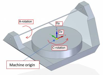 | Machine origin should be placed exactly where the C axis center of rotation is located. Settings:
|
| |
|
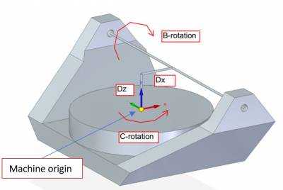 | Machine origin should be placed exactly where the C axis center of rotation is located. Settings:
|
| |
|
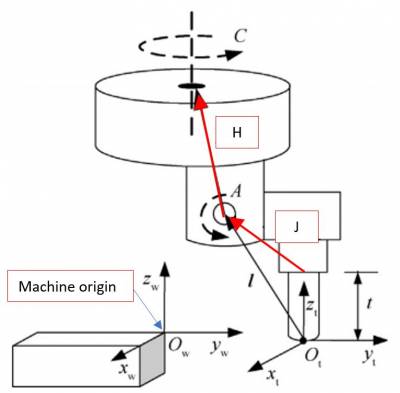 |
Machine origin should be placed considering that the tool holder (tip of the head without a tool mounted) should be at Settings:
|
| |
|
 |
Machine origin should be placed considering that the tool holder (tip of the head without a tool mounted) should be at Settings:
|
13. Acknowledgement
All those who desire to contribute improving this documentation are encouraged to report inaccuracies or incorrect content. Write to the address: support@rosettacnc.com