This is an old revision of the document!
10. Home Search
Home search is the procedure to synchronize the machine reference system.
This operation must be carried out when the CNC loses the machine position (e.g. by turning the machine off or if an emergency occurs).
Home Search may be done in three ways:
- Manual Home Search
- When the CNC Board is in the IDLE state press the status bar button
Homing: 

- G-Code:
- Using command
G102directly in a G-Code program/macro/MDI.
- User Input
- Activating the User Input defined in
Start Axes Homing Inputparameter ofHomingsheet from the menuSetup → Board Settings… → Inputs.
10.1 Machine Reference System and Homing Offset
In order to perform the Home Search procedure, the machine manufacturer has set particular points of the machine: the Machine Zero and the Machine Reference Point.
- Machine Zero
- Machine Zero is the origin point of the machine reference system, set by the machine manufacturer.
- This is the position where the machine coordinate of the axis has a zero value.
- Machine Reference Point
- The machine reference point is a point set by the manufacturer and referred to the machine reference zero.
- This point may be located anywhere on the machine axis and is the point found during home search (in general by homing switch digital input).
- The position of the machine reference point, for each axis, is set by the board setting parameter
Homing: Offset.
- The
Homing: Offsetis the difference between machine zero and the machine reference point.

10.2 Configuring the Axis Home Search
Each axis can be configured to have a specific home search mode, speed, and acceleration.
The Board setting parameter Homing: Mode in the Axes tab specifies the homing mode:
- Disabled
- In this mode, nothing is done when the Homing Search procedure is started.
- The axis position already appears black to indicate that the machine position is synchronized.
- No movement
- In this mode, no movement is commanded to the axis when the Homing Search procedure is started.
- The axis machine position will load with the Board Settings parameter
Homing: Offsetvalue.
- This mode is used when the CNC has no Homing Sensors. Thus the Homing Search procedure is started when the operator manually jogs the axes to the machine reference point.
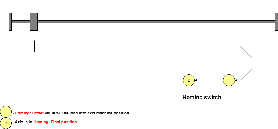
- Falling Edge
- In this mode, the axis moves to the selected direction (set by Board Setting parameter
Homing: Direction) until the axis meets the Homing sensor (Speed is set by Board Setting parameterHoming: Velocity), then reverse direction, decrease velocity by a factor defined by Board Setting general parameterVelocity Dividerand when Homing sensor escapesHoming: Offsetvalue will be load into axis machine position. Finally, the axis is moved toHoming: Final Position.
- This is an example with direction forward and Homing switch normally closed:
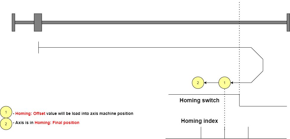
- If the Board Setting parameter
Homing: Index Inputis set, the Homing search procedure uses also the Index Input to archive more precision.


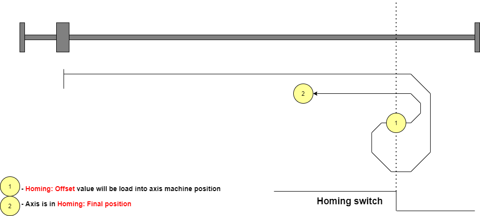
- Rising Edge
- This mode is very similar to Falling Edge but when the Homing sensor escapes, the axis will reverse direction again and load the machine position when the axis meets the homing sensor.
- This mode is used if the Homing sensor has a higher precision in the switching edge opposite to that defined in Falling Edge mode.
- Use this mode in combination with the Board Setting parameter
Homing: Index Inputis not permitted.
- This is an example with direction forward and Homing switch normally closed:

- Absolute
- This mode is used in the EtherCAT servo drive with an absolute encoder.
- No movement is commanded to the axis when the Homing Search procedure is started.
- The axis machine position will be loaded with the resulting value from the
Servodrive positionminus board setting parameterHoming: Offset.
- Absolute with final position
- Is the same as Absolute mode but after load the machine position the axis is moved to
Homing: Final Position.
- Pushing
- This mode is not yet implemented. It is reserved for intelligent servo drive that implements a homing procedure by its firmware.
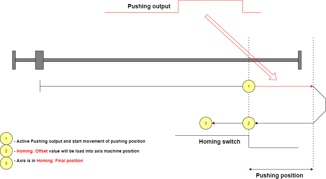
- Pushing Switch Falling Edge
- This mode is very similar to Falling Edge.
- The axis moves to the selected direction (set by Board Setting parameter
Homing: Direction) until the axis meets the Homing sensor (Speed is set by Board Setting parameterHoming: Velocity), then a digital output is activated (selected by Board Setting parameterHoming: Pushing output) generally used to reduce the current in the stepper motor. The axes start a movement ofHoming: Pushing Positionvalue in the same direction to meet a mechanical lock. After that, the digital output will reset and the axis reverse direction to meet the homing sensor again as for Falling Edge mode. This mode is used when the axis step dir signals move two motors drive. The pushing movement is used to align the two axes thanks to the mechanical lock.
- This is an example with direction forward and Homing switch normally closed:

- Pushing Switch Rising Edge
- This mode is very similar to Pushing Switch Falling Edge but when the Homing sensor escapes, the axis will reverse direction again and load the machine position when the axis meets the homing sensor. This mode is used if the Homing sensor has a higher precision in the switching edge opposite to that defined in Pushing Switch Falling Edge mode. Use this mode in combination with the Board Setting parameter
Homing: Index Inputis not permitted.
10.3 Other Configurations
10.3.1 Homing Sequence
When a Home Search is started for All axes it is possible to define the order of axis execution.
Each axis has a Board setting parameter Homing: Sequence. Possible values are from 1 to 6.
Initially, the Home Search the Home Search is started for all axes set to Sequence 1, after axes with Sequence 2, and so on up to Sequence 6.
For a simple three-axis mill machine a typical set is Z-axis with sequence 1 and X and Y axes with sequence 2.
10.3.2 Axis acceleration
For every axis, it is possible to define the acceleration and the deceleration value during Home Search (see Homing: Acceleration and Homing Deceleration).
Please note that deceleration is important if the machine reference position is closed to a mechanical lock.
When the axis is searching the Homing Sensor at Homing: Velocity, it will travel an extra space due to deceleration.
During this space, the axis must not meet the limit switch or the mechanical block.
To help this check the Board settings panel in RosettaCNC software calculate the Homing: Deceleration Space according to deceleration and velocity.
Please check that axis have this space between the machine reference point and limit switch (or the mechanical block).
10.3.3 Homing sensor shared with axis limit
To save machine cost and electrical complexity it is possible to share the same sensor for the Home Search procedure and for the axis Limit Switch.
To enable this share check the appropriate settings in Board Setting Inputs as shown in the following image:

In this way when a Home Search procedure is active the Homing input acts as Homing Sensor, in other cases the Homing input is the limit switch.
Please take care that if you share the sensor it is necessary to set the Homing: Final Position different from Homing: Offset to avoid that at the end of the home search the sensor will not yet active and causes a LIMIT Alarm.
10.3.4 Axes Homing Done Output
It is possible to use a button with a lamp to add to the CNC console the possibility to start Home Search procedure and show the Homing Done status.
To do this:
- Connect the button to a CNC Board User Input and set the Board Settings parameter
Start Axes Homing Inputaccording to the user input number. - Connect the lamp to a CNC Board User Output and set the Board Settings parameter
Axes Homing Doneaccording to the user output number.

10.3.5 Homing Correction Space
When the Home Search procedure for an axis ends, the CNC Board calculates the correction that the procedure has made to the machine position.
This value is displayed in the panel Setup → Board Monitor… → Home Corrections Space
The calculated value can be useful in two cases:
- To evaluate the accuracy of the Home sensor.
- If the Home Search procedure is performed, the machine position is corrected the first time.
- If the Home Search procedure is still run you can evaluate the accuracy and repeatability of your sensor.
- If the sensor were perfect, the Space Correction value would be zero otherwise the calculated correction value is the accuracy of the sensor.
- To check if the stepper motors lose steps.
- First of all, perform a Home Search procedure, then execute a complex G code part program with rapid movements.
- At the end of the execution, perform a Home Search again.
- If the correction value is large it means that steps have been lost in the axis.
- In this case, check that the acceleration or speed is not higher than the motor's capabilities.
10.3.6 Conditions without Home Search Performed
If the Home Search procedure has not been performed, dangerous conditions could occur.
In this case, the machine axis positions are not synchronized and the software limits cannot be applied.
The Allowed Commands without Homing Done, in the menu Setup → Board Settings → General panel, defines the CNC Board behavior in case of Home Search not executed.
Possible parameter options are:
- All
- Every command can be executed.
- Jog at Reduced Speed
- Jog movements are permitted but only at a safe speed (100 mm/min or 100 deg/min).
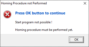
- The execution of a G-Code program/macro/MDI will not be possible and followed by the below UI message.
- None
- Jog movements are not permitted.
- The user must necessarily start a Home Search procedure.
- The execution of a G-Code program/macro/MDI will not be possible and followed by the below UI message.

10.3.7 Invalidate Home Search status
If the CNC Board is controlling an axis with a Stepper Motor, when an ALARM occurs, the Axis Homing Search Done status will be reset.
The axis position, in the Control Software UI, will appear red-colored to indicate that the machine position could be not synchronized.
10.3.8 Disable the Single Axis Home Search
In some CNC configurations, it is never necessary to start a Home Search procedure on a single axis.
In these cases, the Homing button on the status bar can be configured to have the Home All axes function only.
To do this set the field Homing Button Type to Homing of all Axes in the menu Setup → Program Settings.. → ToolBar → Geneal sheet.
10.4 Gantry-Axes
A Gantry axis is a pair of axes that, due to the way the machine is built, must move at the same time and in synchronism.
At the CNC, only the movements of one of the axes must be programmed (the master or main gantry axis).
The other axis (slave gantry axis) is not programmable.
The CNC can manage a maximum of two gantry units. In the following description, reference is made only to gantry 1.
Now we discuss and show the homing search solutions in case of Gantry axis configuration.
Please note that in a gantry configuration during the Home Search it is also necessary to perform a movement to realign the axis, so that the two motors have a position that makes the axis movement without geometric errors.
There are three gantry axis configurations:
- Two drives connected to the same step-dir output.
- This is a very simple solution where two stepper drives are commanded by the same electrical signals. A simple solution to Home search this configuration is to connect a signal to reduce the motor current and a mechanical block near the machine reference point. Please see the description of
Pushing Switch Rising Edgemode for details.- Advantage: very simple solutions
- Disvantage: alignment accuracy depends on the cleanliness of the mechanical block
- Two drives connected to the same step dir output but with an external commutator that can temporarily disconnect one drive.
- In this solution, the step dir output normally commands two motor drives. But during Home Search, there is a moment in which digital output is activated and so only one motor moves while the other keep still. There are also two home switch sensors and the digital output when activated, connects the second sensor to the CNC.
- This way it is not necessary to have a mechanical block. The two motors align using their own homing sensors.
- Advantage: best precision, don't use two step-dir output.
- Disvantage: Need external commutator.
- Two drives connected to two step-dir outputs.
- In this solution, one CNC axis acts as gantry slave. So master maxis and slave axis have their own step dir output. Also every axis have its Home sensor. No extra electrical device are needed for this configuration.
- Advantage: don't need external commutator.
- Disvantage: Use CNC axis for slave gantry.
10.4.1 Gantry Configurations
10.4.1.1 Two drives connected to the same step-dir output.
This is a very simple configuration.
If stepper drivers support the motor current reduction by digital input, connect a RosettaCNC digital output as described in Pushing Switch Rising Edge mode.
Please note that steps for one motor revolution must be the same for the two motors.
Finally, make sure that the fault signals of the two drives are connected to the CNC.
10.4.1.2 Two drives connected to the same step dir output but with an external commutator that can temporarily disconnect one drive.
We call one axis master gantry and another slave gantry.
When the Home search procedure is started, both motors move and the axis uses the home sensor of the master gantry.
Then the external switches are activated and only the “slave gantry” motor moves and performs its home search using its home sensor.
To do this we need two external commutators connected to one RosettaCNC User Output. A commutator when activated interrupts the signals to the master gantry stepper drive.
The second switch is a diverter and when activated the signal of the slave gantry home switch is connected to the CNC (when it is deactivated the home sensor of the master gantry is connected to the CNC).
For the configuration:
- Homing parameters
- Set the axes Homing parameters (for example
Ysheet from the menuSetup → Board Settings… → Axes) as usual.
- Gantries parameters
- Set in
Gantry 1sheet from the menuSetup → Board Settings… → GantriesModetoUse only master motor controlMaster Axisto the master gantry (for exampleY)Homing: ModetoMaster held during alignmentHoming: Digital Outputto the User Output connected with commutatorsHoming: Max Disalignmentto the maximum space that the gantry axis can be misaligned.Homing: Switch Compensationto zero value initially. Then if the geometry of the gantry has errors it is possible to make a small correction by modifying this value instead of moving the position of the homing sensor.Max Disalignmentnot used in case ofUse only master motor controlmode.
Please note that:
- Steps for one motor revolution must be the same for the two motors.
- The fault signals of the two drives are connected to the CNC.
- The homing sensor must have the same logic (NC or NO).
- Same drives (for example the Delta ADS-B2 servo drive) has a digital input that suspends or interrupt the step dir information. In this case, it is possible to simplify the schematics and use only the diverter commutator.

10.4.1.3 Two drives connected to two step-dir outputs.
We call one axis master gantry and another slave gantry.
No the external commutator is needed. Every axis has its home sensor.
For the configuration:
- Homing parameters
- Set the master gantry Homing parameters (for example
Ysheet from the menuSetup → Board Settings… → Axes) as usual. - Set the slave gantry Homing parameters (for example
Asheet from the menuSetup → Board Settings… → Axes) as usual.
- Axis Type parameters
- Set the slave gantry axis ( for example
A) asSlave Axis of Gantry 1inMachinesheet from the menuSetup → Board Settings… → General).
- Gantries parameters
- Set in
Gantry 1sheet from the menuSetup → Board Settings… → GantriesModetoUse slave motor controlMaster Axisto the master gantry (for exampleY)Homing: ModetoMaster held during alignmentHoming: Digital Outputnor used in this case but it can be configured.Homing: Max Disalignmentto the maximum space that the gantry axis can be misaligned.Homing: Switch Compensationto zero value initially. Then if the geometry of the gantry has errors it is possible to make a small correction by modifying this value instead of moving the position of the homing sensor.Max Disalignmentused only in case of EtherCAT control.
