This is an old revision of the document!
6. Board Settings
Some of the following CNC Board Settings are also accessible in the G-Code programming language via the corresponding read-only Named Parameters.
When available, the Named Parameter will be visible next to the parameter description, e.g.:
- Machine Type - [
#<cnc.machine_type>]
All CNC Board Settings, and related named parameters, will be exclusively in the Metric Measurement System.
6.1 General
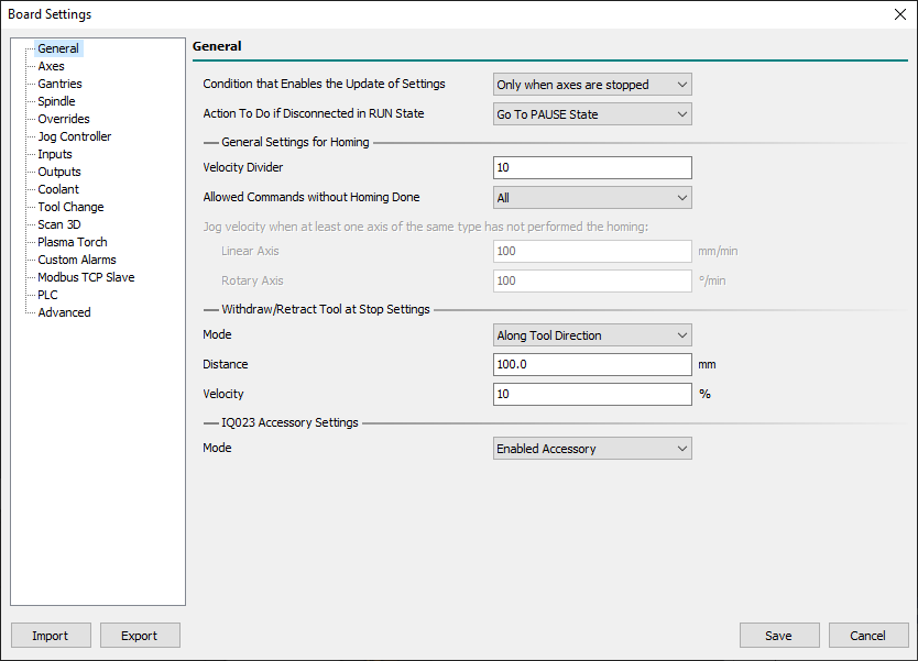
The General panel contains the generic CNC settings.
- Condition that Enables the Update of Settings
- The OK button of the Board Settings panel will be always enabled with Control Software non-connected to the CNC Board.
- When the Control Software is connected to the CNC Board, the status of the OK button depends on the following settings:
- Only when axes are stopped
- The OK button is enabled when there are no movements in execution (CNC in
IDLE/ALARMstate).
- Only when axes are disabled
- The OK button is enabled when Board State is in
WAIT MAIN POWER. - To enter in
WAIT MAIN POWERis necessary to have assigned a digital input to the feature Main Power Input on the Inputs sheet.
- Action To Do if Disconnected in RUN State
- When the connection between the PC and the CNC is interrupted a timeout timer of 4 seconds starts.
- At the end of that, if the CNC is in the RUN state, it automatically switches the CNC to one of the following new states:
- Go To PAUSE State
- The CNC enters in
PAUSEstate.
- Go To ALARM State
- The CNC enters in
ALARMstate.
6.1.0.1 General Settings for Homing
- Velocity Divider
- This is the parameter that defines the ratio between the homing velocity (used when an axis starts the Homing sensor search movements)
- and the final homing switch search movement.
- Example:
- If you set Home Velocity Divider to 10 and the X-Axis Homing Velocity is 6000mm/min, the Homing switch search speed will be 600mm/min.
- Allowed Commands without Homing Done
- Xxx.
6.1.0.2 Withdraw/Retract Tool at Stop Settings
- Withdraw/Retract Tool feature permits to define what CNC has to do when a STOP action is requested to CNC (eg: STOP user input becomes ACTIVE).
- It permits to extract the tool from the stock of a desired distance and velocity.
- After Withdraw/Retract Tool action CNC will execute the STOP action and will enter in
IDLEstate.
- TAKE CARE: If the CNC has not searched for the reference point (homing), the CNC will not carry out the
Withdraw/Retract Toolprocedure.
- Mode
- With the
Modefield is possible to define what type of Withdraw/Retract Tool action will be done:- Disabled
- At the
STOPrequest no Withdraw/Retract action is executed, and the CNC job stops immediately.
- Normal
- At the
STOPrequest the Z-axis moves UP of space defined in theDistancefield. - The requested
Distancewill be limited to Z-axisMax Limitvalue. - This is the common option for Kinematics: Trivial, Independent Rotational Axes, Rotary Table A/C, and Rotary Table B/C.
- Along Tool Direction
- At the
STOPrequest the tool will be extracted following the tool direction vector of measure defined in theDistancefield. - The requested
Distancewill be limited to axesMax Limitvalues. - This is the common option for Kinematics: Tilting Spindle A/C.
- Distance
- The parameter defines the distance from the current tool position to do to extract the tool from stock.
- Velocity
- The parameter defines the percentage of axis/axes max interpolation velocity to be used during the extraction of the tool from stock.
6.2 Axes
The Axes panel contains the CNC Board settings for movement axes.
The panel is subdivided into a variable number of sheets that vary according to what is set in the parameters Machine Type, Kinematics Model, and Axis Type.
6.2.1 Machine
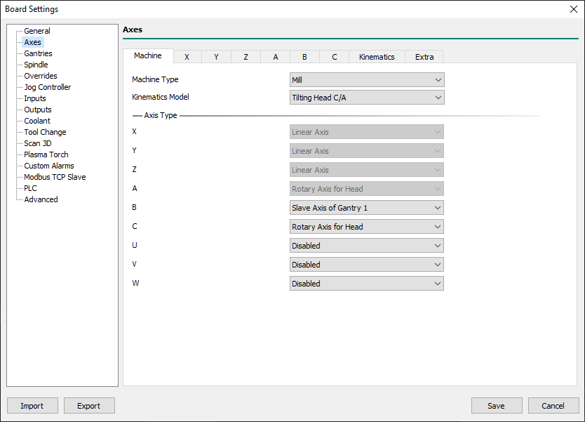
Before beginning to set the axes parameters it is necessary to define the machine configuration.
In this sheet are collected all main settings required to do that.
- Machine Type - [
#<cnc.machine_type>]
- This is the parameter that defines the machine type.
- At the moment the field is disabled and fixed to Mill which means: Mill and Mill/Turn machine.
- Kinematics Model - [
#<cnc.kinematics_model>]
- The CNC Board supports a fixed set of Kinematics to cover all common Mill and Mill/Turn configurations:
- Trivial
- There is a 1:1 correspondence between joints and axes. Most standard milling machines and lathes use the trivial Kinematics model.
- The simplest machines are those in which each joint is placed along with one of the Cartesian axes.
- The toolpath graphic representation will be rendered according to axis positions.
- The Virtual Machine Engine does not support the Trivial model so the VM Parts Geometries will not follow the movements of axes.
- Independent Rotational Axes
- With this Kinematics model, the toolpath will be rendered according to Rotational Axes settings.
- Rotational axes set to
Free Rotary Axiswill not be rendered in toolpath graphic and uses as a linear axis with degrees as um. - Rotational axes set to
Rotary Axis for Tablewill concur to toolpath graphic representation according toKinematicssheet settings. - The Virtual Machine Engine will fully support the VM Parts Geometries following the movements of axes.
- Rotary Table A/C
- Xxx.
- With this Kinematics the Master Rotary Axis is A (turn around X-Axis) and the Slave Rotary Axis is C.
- The Virtual Machine Engine will fully support the VM Parts Geometries following the movements of axes.
- Rotary Table B/C
- Xxx.
- With this Kinematics the Master Rotary Axis is B (turn around Y-Axis) and the Slave Rotary Axis is C.
- The Virtual Machine Engine will fully support the VM Parts Geometries following the movements of axes.
- Tilting Head C/A
- Xxx.
- With this Kinematics the Master Rotary Axis is C and the Slave Rotary Axis is A.
- The Virtual Machine Engine will fully support the VM Parts Geometries following the movements of axes.
- Tilting Head A/B
- Xxx.
- With this Kinematics the Master Rotary Axis is A and the Slave Rotary Axis is B.
- The Virtual Machine Engine will fully support the VM Parts Geometries following the movements of axes.
- Axis Type - [
#<cnc.x.type>..#<cnc.w.type>]
- Depending on the kinematic model chosen, each axis can be set to a range of possible axis types:
- Disabled - [
#<axis.type.disabled>]
- The Axis is disabled and can't be used in G-Code.
- If a disabled Axis is used in the G-Code Program, Macros, or MDI, a compile error will be raised.
- Linear Axis - [
#<axis.type.linear>]
- The Axis is of linear type.
- Free Rotary Axis - [
#<axis.type.rotary_free>]
- The Axis is of the free rotary type.
- A free rotary Axis doesn't have any Kinematics management and its behavior is very close to Liner Axis but use the degree as space units.
- Rotary Axis for Head - [
#<axis.type.rotary_head>]
- Xxx.
- Rotary Axis for Table - [
#<axis.type.rotary_table>]
- Xxx.
- Slave Axis of Gantry 1 - [
#<axis.type.gantry_1>]
- Xxx.
- Slave Axis of Gantry 2 - [
#<axis.type.gantry_2>]
- Xxx.
6.2.1.1 Axes Types for Kinematics Type Mill (Mill/Turn)
- At least two linear axes must be enabled to permits G-Code compilation.
- Axes Types fields in Bold are pre-defined depending on selected Kinematics.
Follow description of Axes Types available with Kinematics of Mill (Mill/Turn) Machine Type:
| Mill Kinematics Type | Axes Types |
|---|---|
| Trivial |
|
| Independent Rotational Axes |
|
| Rotary Table AC |
|
| Rotary Table BC |
|
| Tilting Spindle AC |
|
6.2.2 X .. W
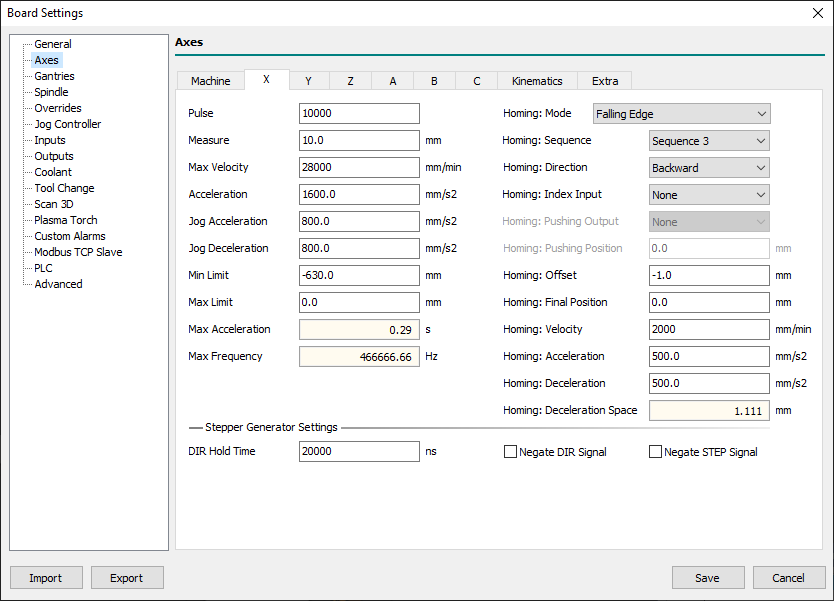
- This panel is the same for axis X to W.
- Available named parameters are reported for X-axis (eg:
#<cnc.x.min_lim>) but are available for every axis from X to W, just change the axis letter.
- Pulse
- Define the impulses necessary to obtain a complete revolution of the motor.
- For steppers motors, this parameter must include the micro-steps so if you have a 200 pulse motor with 8 micro-steps in the driver, you need to set it to 1600.
- For brushless motors, you have to set it to the same pulses set in the driver for a complete revolution.
- Measure
- It is the movement made by the axis with a complete revolution of the motor.
- Max Velocity - [
#<cnc.x.max_vel>] - Defines the maximum velocity value of motor in mm/min and is used with the rapid movements ( Eg:
G00). - It is also the base velocity used to get other CNC movement velocities, as for Jog, Homing, etc.
- Acceleration - [
#<cnc.x.acc>] - Defines the rate of change of interpolated velocity in time and is expressed in mm/s².
- Interpolation acceleration and deceleration share the same value in axis settings.
- The acceleration can be influenced by override when
Override Modeis set toSpeed and Space. - With the
G104command is possible to define a different acceleration/deceleration value for the interpolated point.
- Jog Acceleration
- Defines the rate of change of axis velocity in time during a Jog action acceleration and is expressed in mm/s².
- Jog Deceleration
- Defines the rate of change of axis velocity in time during a Jog action deceleration and is expressed in mm/s².
- Min Limit - [
#<cnc.x.min_lim>]
- Defines the minimum boundary of the axis in mm.
- Max Limit - [
#<cnc.x.max_lim>]
- Defines the maximum boundary of the axis in mm.
- Acceleration Time
- Shows the time required to reach the axis maximum velocity starting from 0.
- Max Frequency
- Shows the maximum frequency used to reach the axis maximum velocity.
- This value can help to understand if the chosen axis configuration is compatible with CNC Board or Axis Driver specifications.
- During the CNC Board order is necessary to choose the maximum STEP/DIR frequency of axes pulse generator between 125/250/500/1000 Hz.
- Every STEP/DIR driver has a maximum frequency acceptable for STEP/DIR signal that must be equal or major than the
Max Frequencyvalue.
- Homing: Mode
- Define the axis homing modality (Home Search chapter).
- Every axis can have a different homing mode choosing from:
- Disabled
- In this mode, nothing is done when the Homing Search procedure is started.
- The axis position already appears black to indicate that the machine position is synchronized.
- No Movement
- In this mode, no movement is commanded to the axis when the Homing Search procedure is started.
- The axis machine position is directly loaded with the parameter
Homing: Offsetvalue. - This mode is used when the CNC has no Homing Sensors.
- Thus the Homing Search procedure is started when the operator manually jogs the axes to the machine reference point.
- Rising Edge
- In this mode, the Homing Search procedure is:
- 1] The axis moves to the selected direction in
Homing: DirectionatHoming: Velocityfeed until the axis meets the Homing sensor. - 2] Then axis reverse direction and decrease velocity by a factor defined by the general parameter
Velocity Divider. - 3] When the Homing sensor escapes, the
Homing: Offsetvalue will be loaded into the axis machine position. - 4] Finally the axis is moved to
Homing: Final Position.
- Falling Edge
- This mode is very similar to Rising Edge but when the Homing sensor escapes, the axis will reverse direction again and load the machine position when the axis meets the homing sensor.
- This mode is used if the Homing sensor has a higher precision in the switching edge opposite to that defined in Rising Edge mode.
- Use of this modality in combination with the
Homing: Index Inputis not permitted.
- Absolute
- This mode is used in the EtherCAT servo drive with an absolute encoder.
- No movement is commanded to the axis when the Homing Search procedure is started.
- The axis machine position will be loaded with the resulting value from the Servodrive position minus
Homing: Offsetvalue.
- Absolute with Final Position
- Is the same as Absolute mode but after the load of the machine position the axis is moved to
Homing: Final Position.
- Pushing
- Xxx.
- Pushing Switch Rising Edge
- Xxx.
- Pushing Switch Falling Edge
- Xxx.
- Homing: Sequence
- Define the homing sequence during a Homing All axes action.
- When a “Homing All Axes” action is required at first all axes with
Sequence= 1 will be referenced. - After will follow all axes with
Sequence= 2 and so on tillSequence= 6. - To improve the axis homing quality is a good choice to have only one axis in the movement at a time.
- Homing: Direction
- Xxx.
- Homing: Index Input
- Xxx.
- Homing: Pushing Output
- Xxx.
- Homing: Pushing Position
- Xxx.
- Homing: Offset
- Xxx.
- Homing: Final Position
- Xxx.
- Homing: Velocity
- Xxx.
- Homing: Acceleration
- Xxx.
- Homing: Deceleration
- Xxx.
- Homing: Deceleration Space
- Xxx.
- Dir Hold time
- Defines the minimum HOLD time, in nanoseconds, of DIR signal in the STEP/DIR generator.
- The default value of 20000 should work for 99.99% of common drivers and don't should be modified.
- The value is however modifiable for very low-quality motor drivers where required minimum time is higher.
- Negate DIR Signal
- Permits to invert DIR signal value and so reverse motor direction.
- This can be useful when the motor movements result inverted in direction to avoid to change cabling.
- Negate STEP Signal
- Permits to invert STEP signal.
6.2.3 Kinematics
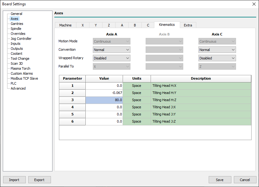
- Use this sheet to configure machine kinematics parameters.
- The proposed fields change and reflect the Kinematics Model and Axis Type defined in Axes→Machine sheet.
- Motion Mode
- Xxx…
- Convention
- Xxx…
- Wrapped Rotary
- Xxx…
- Parallel To
- Xxx…
- Kinematics parameters table
- Xxx…
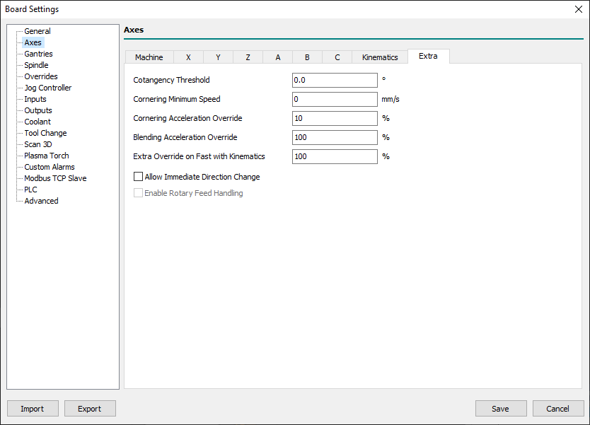
6.2.4 Extra
- Cotangency Threshold
- Xxx…
- Cornering Minimum Speed
- Xxx…
- Cornering Acceleration Override
- Xxx…
- Blending Acceleration Override
- Xxx…
- Extra Override on Fast with Kinematics
- Xxx…
- Allow Immediate Direction Change
- Xxx…
- Enable Rotary Feed Handling
- Xxx…
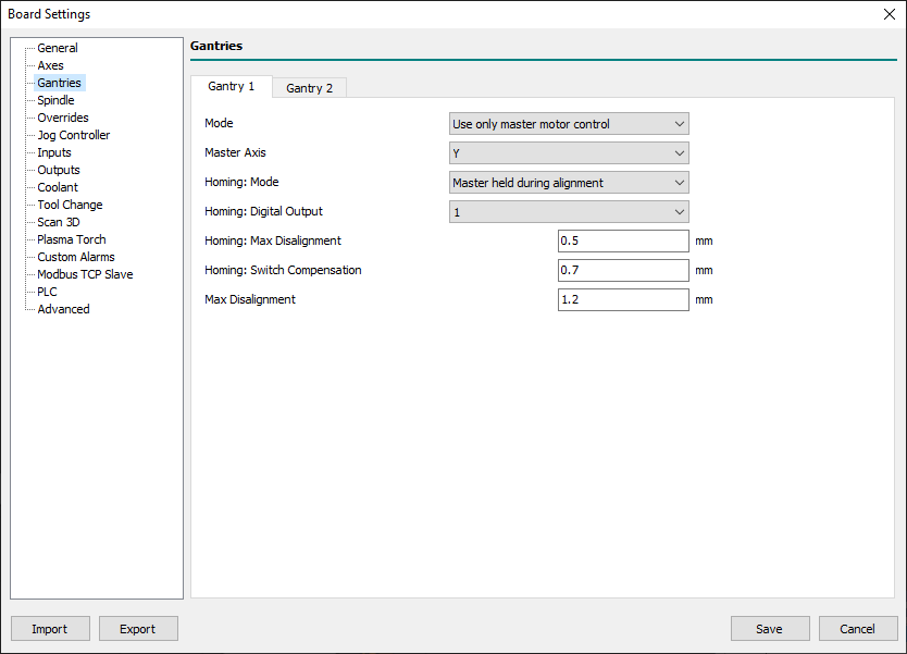
6.3 Gantries
6.4 Spindle
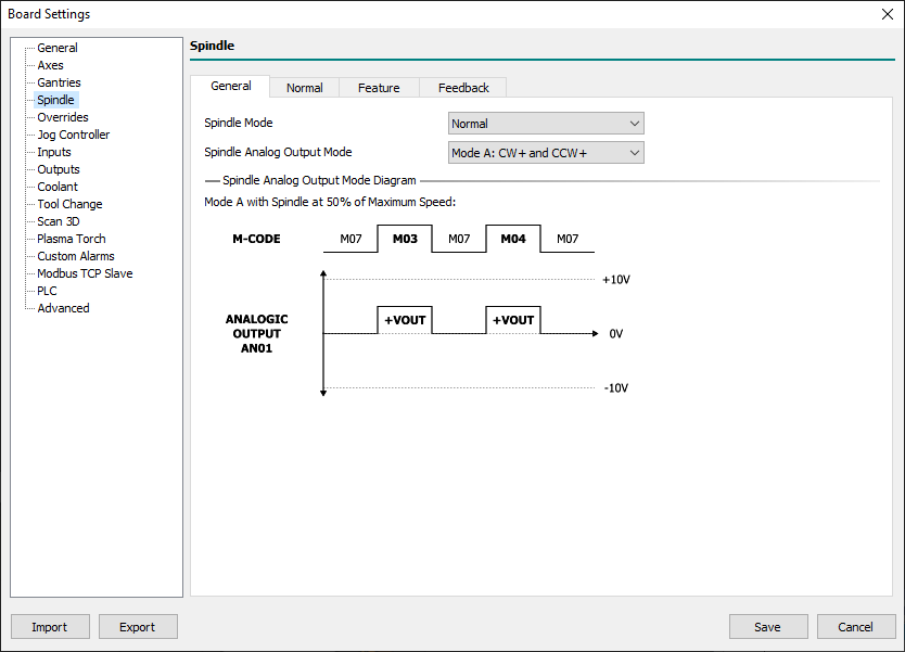
6.4.1 General
- Spindle Mode
- Defines the Spindle type from:
- Normal
- The spindle has only a one-speed range.
- With Automatic Change Ranges
- The spindle system has two or more speed ranges.
- Spindle Analog Output Mode
- Defines the Spindle analog output setting mode:
- Mode A: CW+ and CCW +
- The spindle analog output for clockwise (CW) rotations will use values between 0 to +10V.
- The spindle analog output for counter-clockwise (CCW) rotations will use values between 0 to +10V.
- For a unidirectional spindle, a digital output must be configured to indicate the spindle driver-enabled status.
- For a bidirectional spindle, two digital outputs must be configured to indicate the spindle driver-enabled status and direction of rotation.
- Mode B: CW+ and CCW -
- The spindle analog output for clockwise (CW) rotations will use values between 0 to +10V.
- The spindle analog output for counter-clockwise (CCW) rotations will use values between 0 to -10V.
- For a unidirectional spindle, a digital output must be configured to indicate the spindle driver-enabled status.
- For a bidirectional spindle, two digital outputs must be configured to indicate the spindle driver-enabled status.
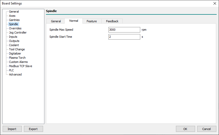
6.4.2 Normal
- Spindle Max Speed
- Defines the maximum speed of the spindle in rpm.
- The entered value corresponds to place 10v in spindle analogic output.
- For e.g. with the field set to 18000 rpm:
- Executing the G-Code
S18000 M03
- The spindle analog output will be placed to 10V (maximum speed) in the clockwise rotation mode.
- Executing the G-Code
S9000 M03
- The spindle analog output will be placed to 5V (half speed) in the clockwise rotation mode.
- Executing a G-Code with an higher RPM value than possible
S30000 M03
- The spindle analog output will be placed to 10V (maximum speed) in the clockwise rotation mode BUT the spindle will reach only its maximum speed.
- Spindle Start Time
- Defines the settling time of the spindle required to reach the programmed speed.
- While waiting for spindle adjustment, the execution of the next block is put on hold.
- The timing starts when:
- The spindle operating status is changed with the
M03/M04/M05commands. - The spindle speed in use is changed with the 'S' command with the spindle on.
- NOTE
- If the spindle supports the feature
At Speed InputorZero Speed Inputthe following behaviors table is applied:
| Spindle State | At Speed Input | Zero Speed Input | Description |
|---|---|---|---|
From M05 to M03/M04 | NO | Spindle Start Time is used to wait for spindle speed settle. |
|
From M05 to M03/M04 | YES | At Speed Input is used to wait for spindle speed settle. |
|
From ON to OFF (M05) | NO | Spindle Start Time is used to wait for spindle speed settle. |
|
From ON to OFF (M05) | YES | Zero Speed Input is used to wait for spindle speed settle. |
|
Switch from M03 or M04 or M04 to M03 |
6.4.3 Feature
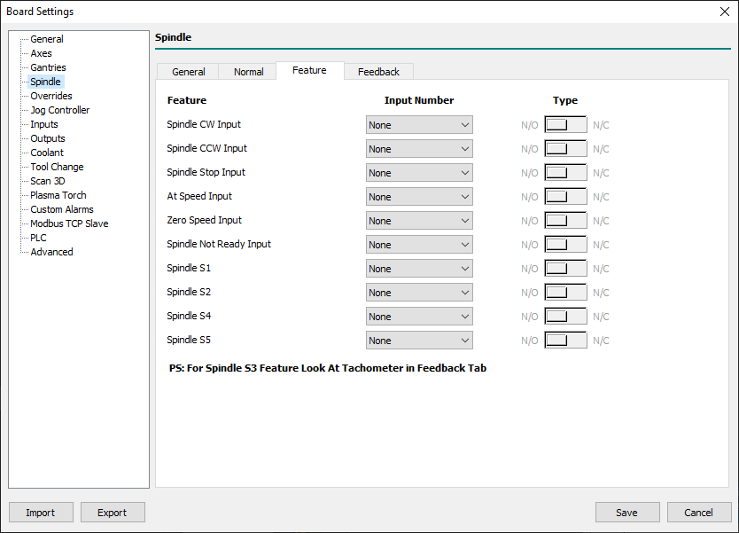
- Spindle CW Input
- Defines the user input to manually start the spindle in the clockwise direction.
- This input is enabled only in CNC Board
IDLEstate. - The input work in TOGGLE mode when
Spindle Stop Inputis not defined.
- Spindle CCW Input
- Defines the user input to manually start the spindle in the count clockwise direction.
- This input is enabled only in CNC Board
IDLEstate.
- Spindle Stop Input
- Defines the user input to manually stop the spindle.
- At Speed Input Input
- Xxx.
- Zero Speed Input
- Xxx.
- Spindle Not Ready Input
- Xxx.
- Spindle S1
- The Tool-holder cone is attached correctly.
- Spindle S2
- The Collet is open.
- Spindle S4 (Optional).
- HSK cone is locked in the correct position.
- Spindle S5 (Optional).
- The Piston is in the upper position.
- If your ATC spindle provides standard
S1..S5output signals you can enable the CNC Board Spindle Control Signals Check management. - The Spindle Control Signals Check (SCSC) management is disabled if Spindle is OFF (
M05) or during tool change in G-Code inner aM107toM108block. - For the base check
S1andS2are mandatory. - In some ATC spindles, the signal
S4orS5is not available, so these checks are optional, and relatedS4/S5fields must be set toNone.
Status modes of the spindle and corresponding outputs:
| STATE | S1 | S5 | S2 | ACTION |
|---|---|---|---|---|
| Collect open | OFF | OFF | ON | The tool-holder is released. |
| Collect closed but tool-holder absent | OFF | ON | OFF | The Tool-holder is not engaged correctly. It is not allowed machining. The electrospindle cannot run. |
| Tool-Holder blocked correctly | ON | ON | OFF | It is allowed machining. |
6.4.4 Feedback
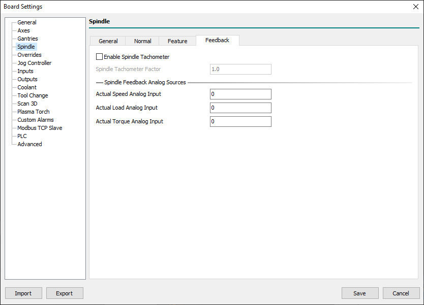
Starting from firmware 1.58 Spindle Feedback is available. Spindle speed can be read back by a digital sensor (Tachometer) or Analog input.
- Tachometer
- Read the frequency of the digital signal connected to TACHO terminal. Frequency is read in 0.01 Hz resolution.
- For example, if you apply a 1Hz signal, control software prints 100rpm as the spindle speed.
- To scale this value for the spindle real speed, use the Spindle Tachometer Factor (from 0.001 to 20).
- Also if you need more scaling factor please visit
Program Settings→ DRO View → Spindle 1/2 → Target Speed
- Analog inputs
- Analog inputs can read Speed, motor current (Load) and Torque.
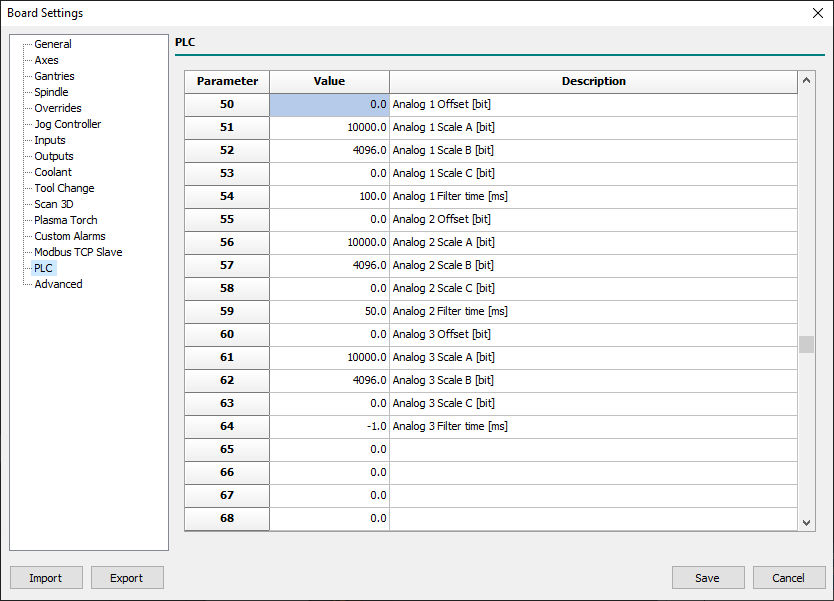
- Set Analog source and PLC parameters from 50 to 64 to scale and filter the source value.
To show spindle feedback data in control software please visit Program Settings→ DRO View panel.
Actually, there is no check on spindle feedback to generate alarms or warnings.
6.5 Overrides
6.5.1 General
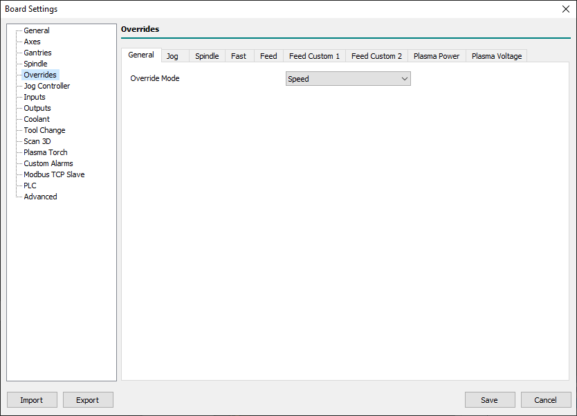
- Override Mode
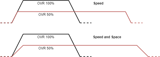
- This is the main setting that defines how CNC Override System has to work with interpolated movements:
- Speed
- With Override Mode set to Speed the override control has effects only on target speed.
- Speed and Space
- With Override Mode set to Speed and Space mode, the override control has effects on target speed and acceleration/deceleration space.
- IMPORTANT NOTE:
- While validating the Board settings, the Override Mode will automatically be changed to Speed if the Feed → Max Override value is greater than 100%.
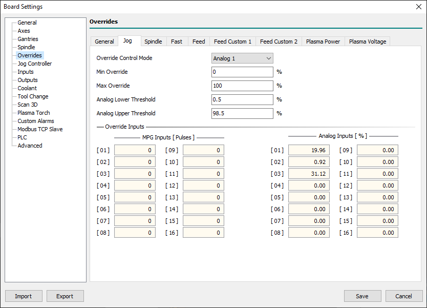
6.5.2 Jog/Spindle/Fast/Feed/Feed Custom 1/Feed Custom 2/Plasma Power/Plasma Voltage
This panel is the same for Jog/Spindle/Fast/Feed/Feed Custom 1/Feed Custom 2 features.
The overrides are active depending by M48/M49/M50/M51 commands following this table:
| Command | Spindle | Fast | Feed | Feed Custom 1 | Feed Custom 2 |
|---|---|---|---|---|---|
M48 | ON | ON | ON | off | off |
M49 | off | off | off | off | off |
M50 | unchanged | ON | ON | off | off |
M50 P0 | unchanged | off | off | off | off |
M50 P1 | unchanged | ON | ON | off | off |
M50 P2 | unchanged | off | off | ON | off |
M50 P3 | unchanged | off | off | off | ON |
M51 | ON | unchanged | unchanged | unchanged | unchanged |
M51 P0 | off | unchanged | unchanged | unchanged | unchanged |
M51 P1 | ON | unchanged | unchanged | unchanged | unchanged |
- Override Control Mode
- Every feature can have a different Override Control Mode choosing from:
- None
- Override Control is disabled and the related OVR value is set at 100%.
- MPG 1..16
- Override Control is managed by the chosen MPG Input source.
- Analog 1..16
- Override Control is managed by the chosen Analog Input source.
- Only at PC
- Override Control is managed with a PC Track Bar.
- Min Override
- Defines the minimum override value.
- Max Override
- Defines the maximum override value.
- The maximum accepted value changes according to the destination of the override:
- 100% for Jog and Fast.
- 300% for Spindle, Feed, Feed Custom 1, and Feed Custom 2.
- Analog Lower Threshold
- Defines the analog lower threshold associated with Min Override's value.
- When analogic input reaches or goes below this value the resulting override value will be placed to Min Override.
- Analog Upper Threshold
- Defines the analog upper threshold associated with Max Override's value.
- When analogic input reaches or goes upper this value the resulting override value will be placed to Max Override.
- MPG Input 1..16
- Defines the MPG Input source for override control.
- Analog Input 1..16
- Defines the Analog Input source for override control.
6.5.2.1 Override Inputs
- MPG Input 1..16
- If Control Software is connected to a CNC Board, these fields will show the current values of connected MPG Inputs to help the end-user to choose the right one.
- Analog Input 1..16
- If Control Software is connected to a CNC Board, these fields will show the current values of connected Analog Inputs to help the end-user to choose the right one.
6.6 Jog Controller
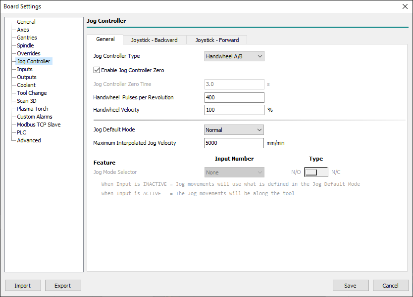
6.6.1 General
- Jog Controller Type
- Defines the Jog Controller Type between:
- None
- None Jog Controller is used.
- Handwheel A/B
- Single Joystick
- A Single Joystick is connected with the CNC Board in the Handwheel dedicated connector.
- Multiple Joystick
- A Multiple Joystick is connected with the CNC Board in the Handwheel dedicated connector.
- Enable Jog Controller Zero
- When the
Jog Controller Typeparameter is set toHandwheel A, the Handwheel Enable Button can be used to set to zero the program position of the selected axis. - To do that is necessary to:
- Check if CNC Board is in the
IDLEstate. - Select the desired axis with the Handwheel Axis Selector.
- Press three times the Handwheel Enable Button in the time defined in the
Jog Controller Zero Timeparameter.
- If all was well done the selected axis program position will be set to zero value and the axis machine position will be placed in the active WCS of the axis.
- Jog Controller Zero Time
- Defines the check time for the
Enable Jog Controller Zeroprocedure.
- Handwheel Pulses per Revolution
- Defines the number of pulses per revolution supplied by the handwheel MPG so that one revolution of the handwheel will move the axis of the desired measurement in x1/x10/x100.
- Normally if the handwheel declares 100 PPR the CNC, reading the 4 fronts of the A/B phases will count 400 (x4) so 400 should be introduced in this field.
- In CNCs for precision mechanics, with an MPG of 100 PPR, it is customary to enter a value of 4000 so that an MPG rotation in x1 gives a displacement of 0.1mm.
- Handwheel Velocity
- Xxx…
- Jog Default Mode
- Xxx…
- Maximum Interpolated Jog Velocity
- Xxx…
- Jog Mode Selector
- Xxx…
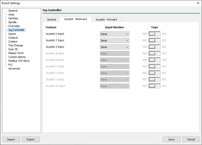
6.6.2 Joystick - Backward
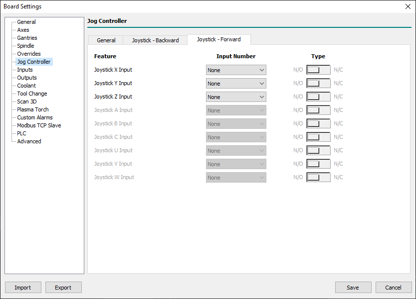
6.6.3 Joystick - Forward
6.7 Inputs
6.7.1 Feature
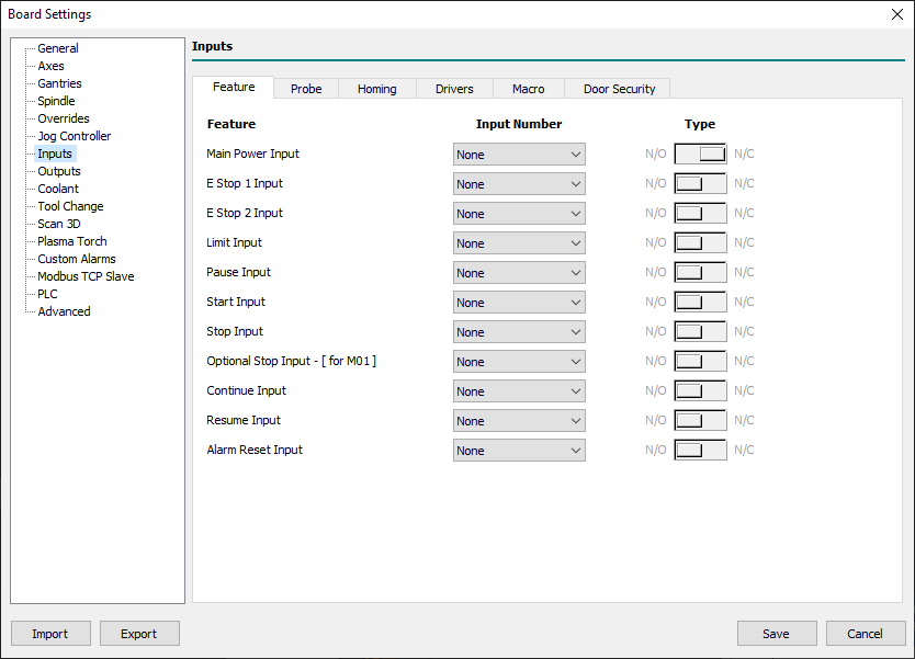
- Main Power Input
- Xxx…
- E Stop 1 Input
- Xxx…
- E Stop 2 Input
- Xxx…
- Limit Input
- Xxx…
- Pause Input
- Define the User Input for the machining Pause feature.
- The Pause Input is checked only when the CNC Board is executing a G-Code program/macro/MDI e CNC Board is or must enter in
RUNstate. - The input works on the level therefore as long as the input is active and the CNC board is executing a G-Code program/macro/MDI it remains in the “PAUSE” state.
- The CNC Board will back to the
RUNstate when User Input will be deactivated. - When Pause Input is active and the operator run a new G-Code program/macro/MDI the CNC Board automatically changes from
IDLEtoPAUSEstate.
- Start Input
- Xxx…
- Stop Input
- Xxx…
- Optional Stop Input - [ for M01 ]
- Xxx…
- Continue Input
- Xxx…
- Resume Input
- Xxx…
- Alarm Reset Input
- Xxx…
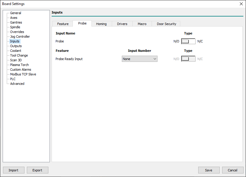
6.7.2 Probe
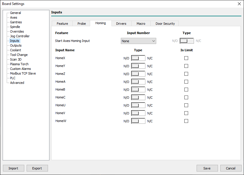
6.7.3 Homing
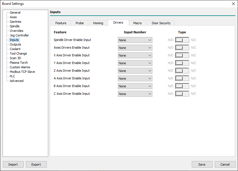
6.7.4 Drivers
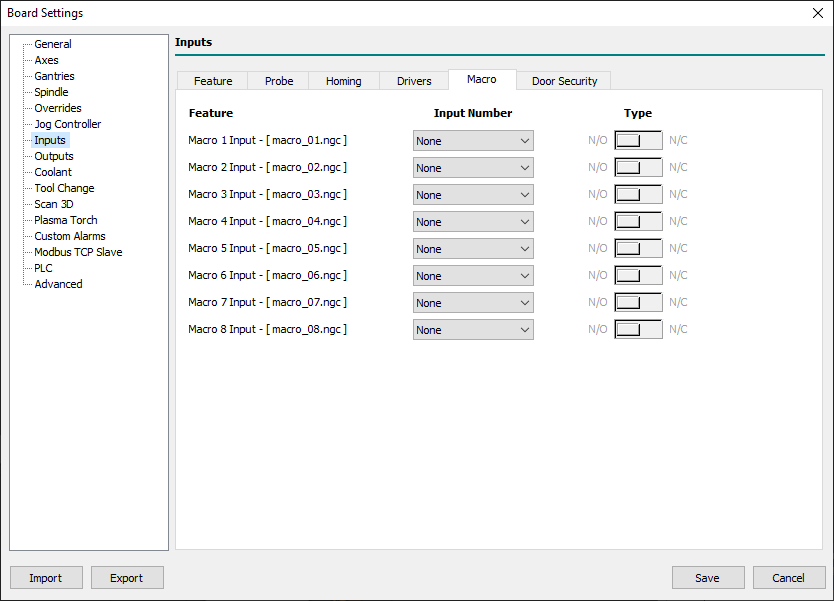
6.7.5 Macro
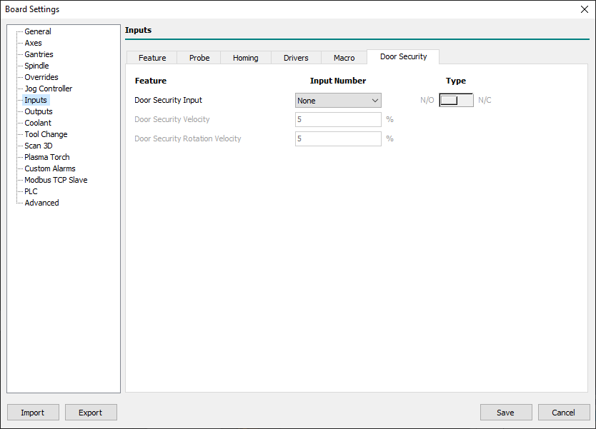
6.7.6 Door Security
6.8 Outputs
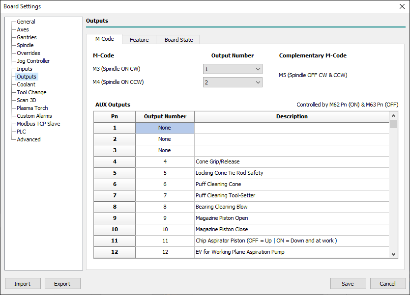
6.8.1 M-Codes
- M3 (Spindle On CW)
- Defines the User Output for spindle ON in the clockwise direction.
- M4 (Spindle On CCW)
- Defines the User Output used for spindle ON in the counter-clockwise direction.
- AUX Outputs
- Defines the association between G-Code AUX outputs and the User Outputs.
- To modify the state of a User Output between G-Code there are two commands:
M62 P<aux_number>(Turn AUX Output ON) andM63 P<aux_number>(Turn AUX Output OFF). - The available G-Code AUX Outputs are 32 and can be mapped to actual User Output using this table.
- To be simple in G-Code reading, when possible, try to keep a 1:1 correspondence between AUX and User Output number, so AUX 1 corresponds to User Output 1.
- However, you can also say that AUX 3 is User Output 1 and a
M62 P3will put ON the User Output 1.
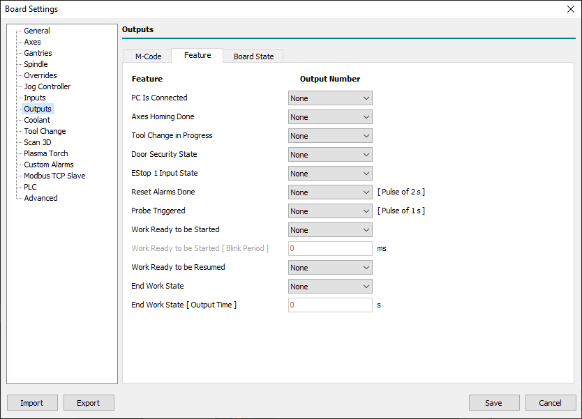
6.8.2 Feature
- PC Is Connected
- Specified user output is
ONwhen a connection between PC Control Software and CNC is established. - When connection falls the output will be
ONfor a timeout time of 4 seconds during that buffered program will continue to work. - If the connection will be restored before timeout finishes the system will continue to work normally.
- Tool Change in Progress
- The specified user output will be
ONduring a tool change procedure invoked with aM06command. - When in the G-Code a
M6is called, the macrotool_change.ngc, with tool change program code, is executed. - At the top of this macro a
M107will inform the PLC the BEGIN of tool change procedure and the specified user output will beON. - At the end of this macro a
M108will inform the PLC the END of tool change procedure and the specified user output will beOFF.
- Axes Homing Done
- When all the enabled axes reach the state of
Homing Donethe specified user output will beON. - When the CNC enters in
ALARMstate the specified user output will beOFF(if CNC is controlling stepper motor).
- Board in WAIT MAIN POWER State
- The specified user output will be
ONwhen the CNC is in theWAIT for MAIN POWERstate.
- Board in RUN State
- The specified user output will be
ONwhen the CNC is in theRUNstate.
- Board in PAUSE State
- The specified user output will be
ONwhen the CNC is inPAUSEstate.
- Board in ALARM State
- The specified user output will be
ONwhen the CNC is inALARMstate.
- Board Not in ALARM State
- The specified user output will be
ONwhen the CNC isn't inALARMstate.
- Door Security State
- Xxx.
- Reset Alarms Done
- The specified user output will be
ONfor 2 seconds when the user resets the Alarms and the CNC exits from theALARMstate. - This output is usually used to reset the fault state in servo drive or spindle inverter.
- Work Ready to be Started
- The specified user output will be
ONwhen a G-Code program is loaded and ready to be started.
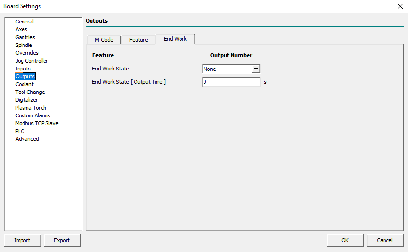
6.8.3 End Work
- End Work State
- The specified user output will be OFF when CNC State changes from SM_IDLE to a working state [SM_RUN, SM_PAUSE, SM_JOG, etc].
- The specified user output will back to ON, after the defined delay time, when the CNC State back to SM_IDLE state.
- If the running CNC activity stops for a STOP/ALARM event the specified user output will be not placed to ON.
- The output
End Work Statewill be switched ON only after thatEnd Work State [ Output Time ]has elapsed with the CNC Board in theSM_IDLEstate.
- End Work State [ Output Time ]
- Defines the delay time from the end of program execution after that the
End Work Statewill be turned ON.
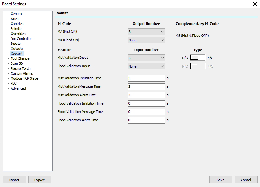
6.9 Coolant
- M7 (Mist ON)
- Defines the number of the user output to use for Mist coolant.
- The Mist coolant output state is controlled in a G-Code program/Macro/MDI using the
M07/M09commands. - If in the menu
Settings→Program Settings→Top Toolbarthe fieldsMist VisibleandMist Enabledare checked when the CNC Board is inIDLEstate the output state can be changed also using related Top Toolbar buttons. - The actual state of Mist coolant is available in G-Code program/Macro/MDI in the parameter
#5153(M7, M9).
- M8 (Flood ON)
- Defines the number of the user output to use for Flood coolant.
- The Flood coolant output state is controlled in a G-Code program/Macro/MDI using the
M08/M09commands. - If in the menu
Settings→Program Settings→Top Toolbarthe fieldsFlood VisibleandFlood Enabledare checked when the CNC Board is inIDLEstate the output state can be changed also using related Top Toolbar buttons. - The actual state of Flood coolant is available in G-Code program/Macro/MDI in the parameter
#5154(M8, M9).
The CNC Board implements also two feedback inputs to control the Pressure/Flow switches signals from Mist & Flood Cooling Systems.
These inputs are optional and when correctly programmed become active during a M07/M08 command or related features in Top Toolbar.
The feedback control operates on M07/M08/M09 commands also if they don't have an assigned user output.
- Mist Input
- Defines the number and logic type of the user input used for the feedback of the Flood Cooling System.
- Flood Input
- Defines the number and logic type of the user input used for the feedback of the Flood Cooling System.
- Mist Inhibition Time
- When the command
M07is executed this is the time in which the Mist feedback signal is inhibited to permit the Mist Cooling System to reach the right pressure.
- Mist Message Time
- When the feedback Mist signal signs a missing Mist pressure to the
Mist Inputstart a watchdog timer. - If the feedback signal is preset continuously for the programmed time a warning message is showed in the Control Software display to warn the end-user of problems in the Mist Cooling System.
- Mist Alarm Time
- When the feedback Mist signal signs a missing Mist pressure to the
Mist Inputstart a watchdog timer. - If the feedback signal is preset continuously for the programmed time the CNC Board enters the
ALARMstate and an error message is showed in the Control Software.
- Flood Inhibition Time
- When the command
M08is executed this is the time in which the Flood feedback signal is inhibited to permit the Flood Cooling System to reach the right pressure.
- Flood Message Time
- When the feedback Mist signal signs a missing Mist pressure to the
Flood Inputstart a watchdog timer. - If the feedback signal is preset continuously for the programmed time a warning message is showed in the Control Software display to warn the end-user of problems in the Flood Cooling System.
- Flood Alarm Time
- When the feedback Flood signal signs a missing Flood pressure to the
Flood Inputstart a watchdog timer. - If the feedback signal is preset continuously for the programmed time the CNC Board enters the
ALARMstate and an error message is showed in the Control Software.
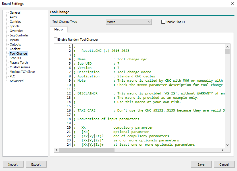
6.10 Tool Change
- In the panel there are 4 fields:
- Tool Change Type
- Defines the way in which the CNC Board manages the
M06command between:- None
- When a
M06command is found by the CNC Board none tool change procedure will be executed and the command will be ignored. - The loaded tool info will be set to
T0, the tool geometry and graphic toolpath color will use the default values. - In this case the H corrector (
G43/G43.1/G43.2/G43.4/G43.7) is correctly managed but requiresH<tool_number>argument to work, otherwise for default will beH0.
- Macro
- When a
M06command is found by the CNC board thetool_change.ngcmacro will be executed. - All actions to get the desired tool change procedure should be placed in that macro.
- The loaded tool info, the tool geometry, and the graphic toolpath color will be set to the tool specified with the
T<tool_number>command. - In this case the H corrector (
G43/G43.1/G43.2/G43.4/G43.7) is correctly managed andH<tool_number>argument is optional.
- PLC
- It is reserved for custom versions of the CNC Board in which the Tool Change management is carried out directly in the CNC instead of the external macro
tool_change.ngc. - Do not use without agreement and support from the CNC Board Support Team.
- Enable Slot ID
- This field is enabled only when the
Tool Change Typeset toMacro/PLC. - The Slot ID feature must be used ONLY if the CNC has an ATC (Automatic Tool Change) System.
- When the field is active it enables the possibility to define the Slot ID in the
Tools Library. - There are two IDs for each tool: Tool ID and Slot ID.
- The Tool ID corresponds to the tool number, therefore Tool ID 1 =
T1, Tool ID 99 =T99. - The Slot ID instead identifies the position of the tool in the tool magazine.
- Tool ID 5 with Slot ID 8 means that tool 5 is in position 8 of the tool magazine, for example, a rack.
- It will then be the task of the macro, suitably written for your machine configuration, to manage the unloading of the tool in use and the withdrawal of the new one from the slot specified during the macro call.
- Macro
- The Macro sheet contains the code of the tool change macro.
- The G-Code editor integrated into the panel allows you to examine and edit the macro contents.
- However, it is possible to examine and modify this macro also through a normal ASCII Text Editor such as NotePad++ by directly accessing the file in the folder:
%APPDATA%\RosettaCNC-1\machines\<your_machine_name>\macros\tool_change.ngc.- To fastly get into the macros folder you can also use the menu
File → Open Macros Folder.
- Enable Random Tool Changer
- The option is currently disabled but foreseen in the CNC Board to manage the case of tool changes where the Slot ID is random and corresponds to the first free and available one.
6.11 Scan 3D
6.11.1 Probe
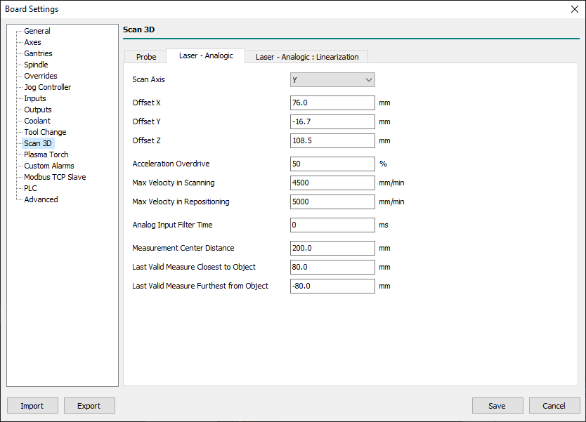
6.11.2 Laser - Analogic
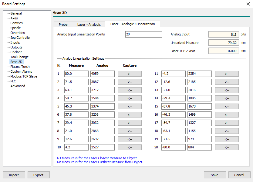
6.11.3 Laser - Analogic : Linearization
6.12 Plasma Torch
Xxx… (breve descrizione sulle possibilità plasma della CNC).
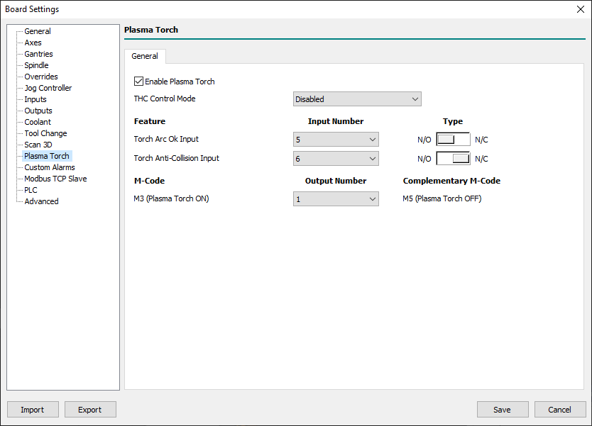
6.12.1 General
- Enable Plasma Torch
- Enables the CNC Board Plasma Torch management.
- If the plasma torch management is disabled and a
M17orM18command is executed in the G-code, the following alarm will appear:
- THC Control Mode
- Xxx…
- Torch Arc Ok Input
- Defines the user input and the type of logic demanded to receive the ARC OK command signal from the external THC control unit.
- Torch Anti-Collision Input
- Defines the user input and the type of logic dedicated to managing the torch collision signal and is optional if the THC control unit don't implement it.
- When the THC is active (
M17) the CNC Board continuously monitors the signal and if it indicates a collision, the machining is immediately stopped and the alarm would appear: - <place image here>
- M3 (Plasma Torch ON)
- Defines the number of user output that sets the plasma torch state.
- This output will be activated on M3 command when a Plasma Tool is enabled otherwise will enable the output set for Spindle clockwise direction.
- If using a Spindle + Plasma Torch system, take care that this output is not the same as clockwise or counterclockwise Spindle activation.
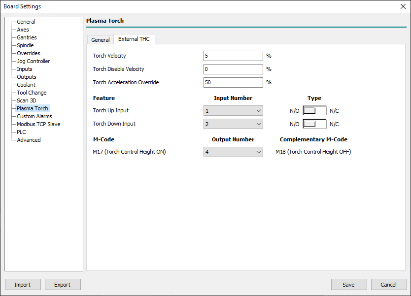
6.12.2 External THC
- Torch Velocity
- Defines the Z-Axis velocity when it is controlled by the THC.
- It is a percentage value of Z-Axis maximum speed.
- Torch Disable Velocity
- Defines a percentage of the feed set in which the THC control is automatically disabled.
- Place zero in this field to disable the function.
- Torch Acceleration Override
- Defines the acceleration of the Z-Axis during the THC check.
- The 100% value means use the full Z-Axis
Acceleration Timeprogrammed value. - The 50% value means use the half Z-Axis
Acceleration Timeprogrammed value.
- Torch Up Input
- Defines the user input and the type of logic demanded to receive the UP command signal from the external THC control unit.
- When THC is enabled (
M17) the Z-Axis movements are demanded to THC which ask, in this way, to CNC Board to move UP the Z-Axis.
- Torch Down Input
- Defines the user input and the type of logic demanded to receive the DOWN command signal from the external THC control unit.
- When the THC is active (
M17) the Z-Axis movements are demanded to THC which ask, in this way, to CNC Board to move DOWN the Z-Axis.
- M17 (Torch Control Height ON)
- Defines the number of user output that is activated when Z-Axis is controlled by the THC device.
- This field is not mandatory.
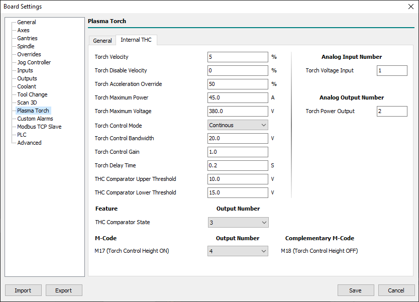
6.12.3 Internal THC
- Torch Velocity
- Xxx…
- Torch Disable Velocity
- Xxx…
- Torch Acceleration Override
- Xxx…
- Torch Maximum Power
- Xxx…
- Torch Maximum Voltage
- Xxx…
- Torch Control Mode
- Xxx…
- Torch Control Bandwidth
- Xxx…
- Torch Control Gain
- Xxx…
- Torch Delay Time
- Xxx…
- THC Comparator Upper Threshold
- Xxx…
- THC Comparator Lower Threshold
- Xxx…
- THC Comparator State
- Xxx…
- THC Comparator State
- Xxx…
- M17 (Torch Control Height ON)
- Xxx…
- Analog Input Number
- Xxx…
- Analog Output Number
- Xxx…
6.13 Custom Alarms
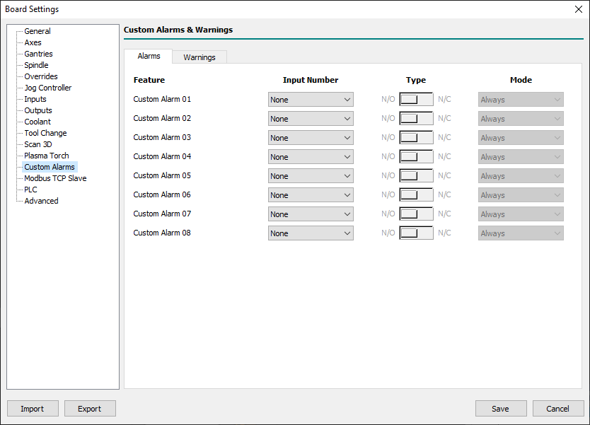
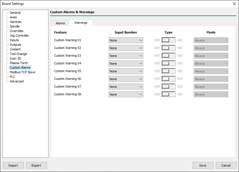
This panel allows you to define Custom Alarms and Warnings associated with a digital User Input.
Each Alarm or Warning can be configured to be issued at a specific level between the Type and Mode fields.
The texts of Alarms and Warnings, displayed when triggered, must be entered in the panel Setup → Program Settings… → Custom Alarms.
6.13.1 Alarms
- Input Number 01..08
- Defines the User Input associated with the custom Alarm 01..08.
- Type
- Defines the type of User Input between:
- NO
- NO = Normally Open.
- This is the normal state of User Input where the Alarm is not raised.
- When the User Input change from the LOW to the HIGH state the related Alarm will be raised.
- NC
- NC = Normally Closed.
- This is the normal state of User Input where the Alarm is not raised.
- When the User Input change from the HIGHT to LOW state the related Alarm will be raised.
- Mode
- Defines when the Alarm check is enabled between:
- Always
- The Custom Alarm check is always enabled.
- RUN
- The Custom Alarm check is enabled only when the CNC Board is in the
RUNstate.
- CHANGE TOOL
- The Custom Alarm check is enabled only when the CNC Board is in the
CHANGE TOOLstate.
6.13.2 Warnings
- Input Number 01..08
- Defines the User Input associated with the Custom Warning 01..08.
- Type
- Defines the type of User Input between:
- NO
- NO = Normally Open.
- This is the normal state of User Input where the Warning is not raised.
- When the User Input change from the LOW to the HIGH state the related Warning will be raised.
- NC
- NC = Normally Closed.
- This is the normal state of User Input where the Warning is not raised.
- When the User Input change from the HIGHT to LOW state the related Warning will be raised.
- Mode
- Defines when the Warning check is enabled between:
- Always
- The Custom Warning check is always enabled.
- RUN
- The Custom Warning check is enabled only when the CNC Board is in the
RUNstate.
- CHANGE TOOL
- The Custom Warning check is enabled only when the CNC Board is in the
CHANGE TOOLstate.
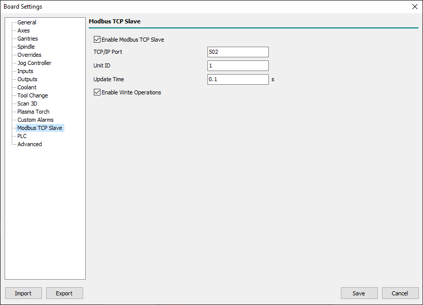
6.14 Modbus TCP Slave
The CNC Board is equipped with a Modbus® Slave TCP/IP for exchanging information with devices such as a PC/PLC/etc.
This function is interesting for implementing machine logic within the PLC or other device that implements a Modbus® TCP/IP Client.
Modbus messaging on TPC/IP implementation guide is available at this LINK
More information about the registers published by the Modbus® Slave is available in RosettaCNC plugin Modbus
- Enable Modbus TCP Slave
- Enables the Modbus TCP Slave feature.
- TCP/IP Port
- Listening port for Modbus TCP Slave.
- The default value of the standard is 502.
- The following ports cannot be used: 1460, 5001, 5002, 5003, and 5004.
- Unit ID
- Unit ID for Modbus protocol.
- Update Time
- Update time for exchanged data.
- Valid range is from 0.1 to 5.0 seconds.
- Enable Write Operations
- Enable write operations in Modbus registers.
6.15 PLC
The grid allows you to define PLC Parameters used to customize some default settings of the CNC Board Firmware.
For example, the filtering time of analog inputs, or their scaling value, can be changed when these are used for special purposes.
All values are in Floating-Point even when Boolean or Integer values are to be expressed.
In order to avoid undesirable effects, do not change the default values except under the supervision of one of our technicians.
