7. Feed Management
7.1 Rotary Axes Indexer option
If you set the axis to be an Indexer the G-code interpreter will check the G-code and ensure that the axis is moved only with sigle axis fast moves (G0).
The most obvious case for indexing is to gain better access to the part.
7.2 Rotary Axes Continuous Machining
RosettaCNC supports “Rotary Axes Continuous Machining”, which may also be referred to as “Rotary Axes Contouring”.
It enables all new kinds of machining and can also make existing jobs run faster and require less setup.
Single-axis feedrate moves
To perform feedrate moves on the rotary fourth axis G1 can be used, likewise a linear axis, except that distances are in degrees and feedrates are in degrees per minute.
Multi-axis feedrate "mixed moves"
“Mixed moves” are moves which combine rotary axis movement with linear axis movement.
These moves too are programmed like normal linear moves. However, the formula for calculating the combined inch/degree feedrate is a little more complicated.
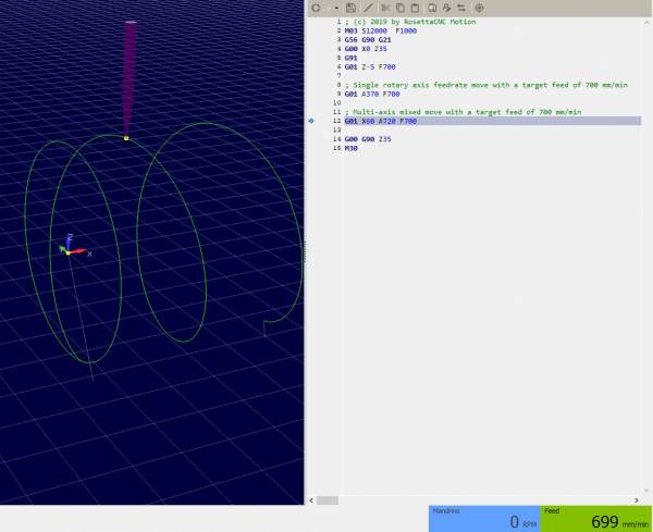
RosettaCNC "mixed moves feed handling" feature
If the origin of the rotational axis has been specified the feature named “Rotary Feed Handling” can be enabled.
In this case RosettaCNC considers the distance from the origin of the rotational axis to the tool to perform a motion with the specified target speed.
Notes:
- RosettaCNC considers even the tool offset if enabled with
G43. - No need to use any special macro or perform complicated calculations
Standard macro approach
Since RosettaCNC provides Macro B compatible parametric programming we have created for you an arithmetic function within the control that determines feed rate in degrees per minute.
The function accepts input arguments in the form of desired per minute feed rate, the tool’s position relative to the center of rotation, the amount of angular departure and the variable number in which the calculated degrees per minute feed rate will be stored. The function will calculate the degrees per minute feed rate based on the input data and store the results in the specified variable. This variable can be used to specify the feed rate in the rotary axis command.
The code of the macro is the following one
; Calculate feed  axis based on both linear and rotary movement
; A = #1 = rotary axis movement (optional argument)
; X = #24 = linear movement (optional argument)
; D = #7 = distance from center
; F = #9 = desired tool feed
; R = #18 = return value
O1001
    IF [#24 EQ #0] THEN  #24 = 0
    IF [#1 EQ #0] THEN  #1 = 0
    IF [#1 EQ 0] THEN1
        #[#18] = #9
    END1
    IF [#24 EQ 0] THEN1
        #100 = [3.1416 * 2 * #7]            ; calc circumference
        #100 = [[#100 * ABS[#1]] /360]      ; calc rotary length
        #[#18] = [ABS[#1] / [#100 / #9]]
    END1
    IF [[#1 NE 0] AND [#24 NE 0]] THEN1
        #100 = [3.1416 * 2 * #7]            ; calc circumference
        #100 = [[#100 * ABS[#1]] /360]      ; calc rotary length
        #100 = SQRT[[#100*#100]+[#24*#24]]  ; calc total space
        #100 = [#100/#9]                    ; calc movement time [min]
        #[#18] = [ABS[#24]/#100]            ; new linear feed
    END1
M99
It could be stored in a dedicated file in the macros folder and used as follows
; (c) 2019 by RosettaCNC Motion
M03 S12000  F1000
G56 G90 G21
G00 X100 Z35
G91
G01 Z-5 F700

; Single rotary axis feedrate move with a target feed of 700 mm/min
G65 P1001 A370 F700 D30 R101
G01 A370 F#101

; Multi-axis mixed move with a target feed of 700 mm/min
G65 P1001 A-720 X-60 F700 D30 R101
G01 X-60 A-720 F#101

G00 G90 Z35
M30
