12. RTCP
In 5-Axis Continuous Machining (3 linear axes + 2 rotary axes) the main goal is to keep under control the contact point between tool and piece.
When generating the part-program, the CAD-CAM system calculates the points coordinates on the piece surface and the rotary axes orientation (swiveling head or table).
The CNC Board, thanks to the optional RTCP (Rotating Tool Center Point) feature, calculates the axes' movements in order to keep the tooltip in the right position, taking automatically into account the machine geometry and the tool length.
This automatic calculation allows to execute the same part-program with different tool lengths or different machine geometry without needing a regeneration of the part-program with the CAD-CAM:
- Less downtime.
- Increased productivity.
- Increased toolpath precision than Systems without RTCP.
- Better Feed control of TCP Feed than Systems without RTCP.
- The working WCS can be changed anytime without back to CAD/CAM for Stock placement.
12.1 Gcode
G43.4
G43.4 is the standard G code to enable RTCP compensation.
When RTCP is enabled using G43.4 the CNC compensates tool offsets and machine kinematics but not the tool radius.
G54 G49 G21
G0 X0 Y0 Z110 A0 C0

; Enable RTCP for the tool 1.
; RTCP will compensate machine kinematics and tool length.
G43.4 H1 ; To compensate for the loaded tool write H#5134
F1000
G1 A45 ; The CNC will rotate axis A keeping the tool tip in the current position.
Z0
X100
C-90 ; The CNC will rotate axis C keeping the tool tip in the current position.
Y100
M2
 |  |
|---|
G43.7
G43.7 is similar to G43.4 but the user can override the values of the tool offsets.
Overriding tool offsets can be useful to compensate for the tool radius when the cutting point of the tool is known.
This G code is useful to write easily G-code programs by hand when a saw tool is used.
G54 G49 G21
; Assumptions:
; 1) The saw is already in the desired position.
; 2) We have just stored the current TCP position in the G54 WCS
;    so that our program is based on the point where the saw touches
;    the material
G43.7 H1 Y[-1 *[#5410/2]] ; The "Y[-1 *[#5410/2]]" is used to enable the radius compensation for the current saw.

#10 = 500
#100 = [#10*cos[-#5006]]
#101 = [#10*sin[-#5006]]

F1000
G1 X#100 Y#101 Z0
G1 C0  F1000
A90
#10 = 500
#100 = [#10*cos[-#5006]]
#101 = [#10*sin[-#5006]]
G91
G1 X#100 Y#101 F5000
G90
M2
 |  |
|---|
Example
Suppose you are looking from the right side a C/A 5-Axis Head and you set a target position of -90 for axis A.
| RTCP disabled | RTCP enabled |
|---|---|
 |  |
- RTCP disabled:
A-90.0causes a movement of axis A without any linear axis movements that would keep the tool in contact with the part. - RTCP enabled:
A-90.0causes the swing of -90° for the axis A and the displacements of the linear axes to maintain the tool tip at the same location
12.2 Supported Kinematics
Machines with 5 axes may have different types of kinematic motions to be controlled. The CNC Board supports:
- Rotary Table A/C with vertical head
- Rotary Table B/C with vertical head
- Tilting Head C/A
- Tilting Head A/B
| Model | Settings |
|---|---|
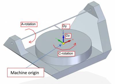 | Machine origin should be placed exactly where the C axis center of rotation is located. Settings:
|
| |
|
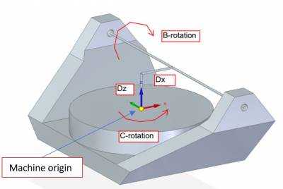 | Machine origin should be placed exactly where the C axis center of rotation is located. Settings:
|
| |
|
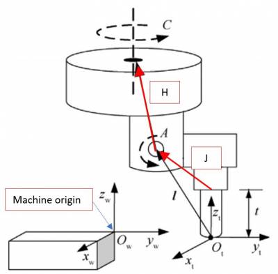 |
Machine origin should be placed considering that the tool holder (tip of the head without a tool mounted) should be at Settings:
|
| |
|
 |
Machine origin should be placed considering that the tool holder (tip of the head without a tool mounted) should be at Settings:
|