Indice
RosettaCNC - Control software
Information
| |
|||
| Document: | MDUROSETTACNCCONTROLSOFTWARE | ||
|---|---|---|---|
| Description: | RosettaCNC Control SOFTWARE | ||
| Link: | https://wiki.rosettacnc.com/en/software/mdurosettacncsoftware | ||
| Release documento | Descrizione | Note | Data |
| 01 | First release | / | 18/05/2021 |
| 02 | Update | / | 16/01/2022 |
| 03 | Update | / | 10/11/2022 |
References
This manual explains the Control Software used by the RosettaCNC Board.
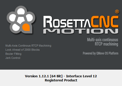
All the implementation details refer to the software version: 1.12.1.
The current version of the Control Software can be identified by opening the Help → About menu:
 |
1. System Overview
The RosettaCNC System is composed of 4 main parts:
- The CNC Board.
- The Control Software.
- The Communications Service.
- The Plugin Industry 4.0 (optional).
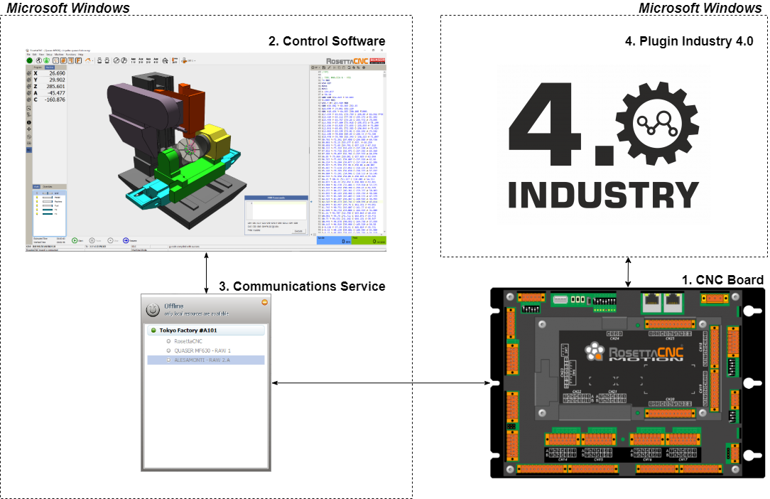
1.1 The CNC Board
The CNC Board, or simply the “Board”, is a complete CNC controller built over a proprietary powerful Industrial Real-Time Operating System called QMOS.
It contains all features to manage independently the Axes Interpolations, the Smoothing Engine, Jerk Control, and RTCP algorithms, the Digitals and Analogs I/O, the Modbus, and EtherCAT Fieldbus, and so on.
The Board communicates with the other parts of the system using a fast and secure multi-port ETH connection.
1.2 The Control Software
The Control Software is a powerful UI Environment, for Windows OS used to manage and program the Board.
Through the Control Software, you can load and create the G-Code programs, configure and monitor the Board, and simulate/analyze a program with virtual machines before running it with the Board.
1.3 The Plugin Industry 4.0
To meet the requirements of Industry 4.0 a dedicated plugin for RosettaCNC has been developed.
With this plugin your CNC can:
- Communicate with other systems using the OPC-UA secure industrial protocol.
- Send files to your CNC using FTP or the secure FTPES.
- Send alarm notifications using emails.
- Record CNC events on a CSV file.
Using the OPC-UA protocol almost all CNC data can be read from a standard OPC-UA client.
2. Control Software
| Command | Spindle OVR | Fast OVR | Feed OVR | Feed OVR Custom 1 | Feed OVR Custom 2 |
|---|---|---|---|---|---|
M48 | ON | ON | ON | off | off |
M49 | off | off | off | off | off |
M50 | unchanged | ON | ON | off | off |
M50 P0 | unchanged | off | off | off | off |
M50 P1 | unchanged | ON | ON | off | off |
M50 P2 | unchanged | off | off | ON | off |
M50 P3 | unchanged | off | off | off | ON |
M51 | ON | unchanged | unchanged | unchanged | unchanged |
M51 P0 | off | unchanged | unchanged | unchanged | unchanged |
M51 P1 | ON | unchanged | unchanged | unchanged | unchanged |
3. CNC Board States
 |
The active CNC Board state is always visible in the status bar of the Control Software as marked in the red rectangle.
The CNC Board can be in one of the following internal states:
- INIT
- Waiting for internal state initialization.
- The CNC Board is in the initialization phase of the main modules.
- INIT FIELDBUS
- Waiting for the EtherCAT Fieldbus to be initialized (all slaves in OPERATIONAL).
- The CNC Board is in the initialization phase and waiting for the EtherCAT Fieldbus to be initialized.
- ALARM
- When the CNC Board catches an alarm condition stops any activity and enters in
ALARMstate. - In this case:
- The running G-Code Program\Macro\MDI is stopped in the current block.
- Any other activity (JOG, Homing, Scan 3D, etc) is stopped immediately.
- The axes' movements are stopped without deceleration ramps.
- The Homing references, if CNC doesn't use absolute encoders with EtherCAT configuration, are invalidated and back in the red state.
- All AUX outputs are automatically placed in the OFF state.
- This state remains till all alarms cause are removed and the alarms list is cleared.
- To clear alarms list:
- Activate the user input with assigned the feature
Reset Alamars. - Press
CTRL+F11in the Control Software. - Double click on the alarm message to who Alarms panel and click the Reset button.
- From the main menu
- IDLE
- The CNC Board is in the IDLE state ready to execute a command.
- HOMING
- The CNC Board is in the HOMING state and one or more axes are doing the homing research.
- JOG
- The CNC Board is in the JOG state and one or more axes are doing a Jog movement.
- RUN
- The CNC Board is in the RUN state and a G-Code Program/Macro/MDI is executing.
- PAUSE
- The CNC Board is in the PAUSE state and a G-Code Program/Macro/MDI is in pause.
- LIMIT
- The CNC Board is in the LIMIT state because one or more LIMIT digital input is active.
- SCAN3D
- The CNC Board is in the SCAN3D state.
- SAFETY IDLE
- Jog is allowed with reduced speed.
- CNC is in SAFETY state and JOG movements are allowed with reduced speed.
- CHANGE TOOL
- CNC Board is performing a tool changing procedure.
- SAFETY
- All axes are disabled, the main power can be switched off without causing an alarm.
- WAIT MAIN POWER
- The CNC Board enters in this state when the
- RETRACT
- The CNC Board enters into this state depending on the
Withdraw/Retract Tool at Stop Settingsparameters defined in theBoard Settings(See Description). - Withdraw/Retract Tool feature permits to define what CNC has to do when a STOP action is requested to CNC (eg: STOP user input goes active).
- It permits to extract the tool from the stock of a desired distance and velocity.
- After Withdraw/Retract Tool action CNC will execute the STOP action and will enter in
IDLEstate.
TAKE CARE: If the CNC has not searched for the reference point (homing), the CNC will not carry out the Withdraw/Retract Tool procedure.
Control Software has two extra states depending on the connection state with the CNC Board or the state of the Simulator:
- DISCONNECTED
- CNC is not connected with the Control Software.
- SIMULATOR
- The Control software is in Simulator state.
- To enter in the Simulator state is not necessary to be connected with a CNC Board.
- If the Control Software is connected with a CNC Board to enter in Simulator state the board must be in IDLE state.
4. Program Settings
Program Settings panel permits to sets the Control Software behavior.
The following images represent the settings captured from the default machine just as after a clean installation and are only for samples.
4.1 General
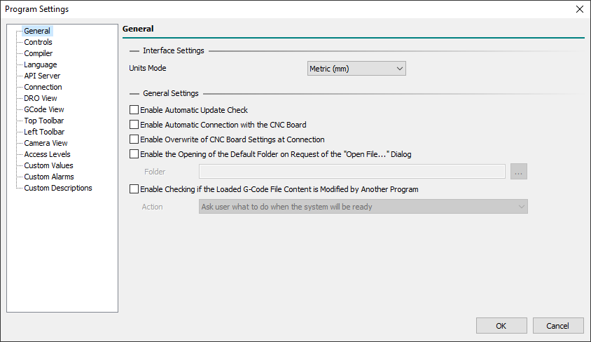
4.1.0.1 Interface Settings
- Units Mode
- Permits to define the Units Mode used in the Control Software UI between
Metric (mm)andImperial (in). - It ONLY sets the measures representation in the UI so, in the G-Code, the Units Mode can be defined with a
G20orG21and can be different than UI. - During the G-Code Program/Macro/MDI execution,
G20andG21commands can be freely mixed but UI representation will be fixed to this setting. - All fields and settings of the UI are affected by the Units Mode except for Board Settings which are always expressed in the Metric System.
4.1.0.2 General Settings
- Enable Automatic Update Check
- If enabled actives automatic check, at Control Software start and every 3 minutes, of online updates.
- If an update is available a blinking advice message will be shown in Control Software Status Bar.
- If disabled you can manually check if an update is available with the main menu
Help → Check for Updates. - Update Manager checks for online updates regarding only the current version, eg: 1.9.x search only for 1.9 branches.
- The update Check feature can be locked, to the end-user, using Access Levels settings.
- PS: During the Update phase, if Windows UWF Status is found Enabled, the update procedure will be stopped because is not possible to update permanently files in a UWF protected disk.
- Enable Automatic Connection with the CNC Board
- If enabled it actives automatic connection with CNC Board at Control Software starts.
- Enable Overwrite of CNC Board Settings at Connection
- When Control Software opens a connection with CNC Board it checks if Board Settings in CNC Board are the same as Board Settings stored on Control Software.
- If settings are different, and this option is enabled, the Control Software automatically sent Board settings on Control Software to CNC Board.
- If this option is disabled, a prompt user dialog will show the state and will ask the end-user to Download Control Software Board Settings to CNC Board or Upload CNC Board settings to Control Software.
- This feature is very useful when the same CNC Board is used in a CNC machine that uses more than one configuration, such as a 3-Axis vertical spindle or a 4-Axis horizontal spindle.
- Enable the Opening of the Default Folder on Request of the “Open File…” Dialog
- If enabled it permits to define the default folder open on Request of the main menu
File → Open File…dialog or pressing theF12key. - Special Windows folder shortcuts can be used here (for eg.
%APPDATA%, to reach the user application data folder).
- Enable Checking if the Loaded G-Code File Content is Modified by Another Program
- If enabled it permits to define how to update the loaded G-Code file when a new version is available.
- This happens, for eg., when a user asks CAM to create a new G-Code output file or when the G-Code file is modified by the user with a text editor.
- Four different actions could be chosen:
- Ask user what to do if the system is ready
- When the loaded G-Code program changes externally, and the CNC is in IDLE, a prompt dialog asks the user what to do.
- Ask user what to do when the system will be ready
- When the loaded G-Code program changes externally, and the CNC is not in IDLE the check system waits for CNC IDLE, then a prompt dialog asks the user what to do.
- Load automatically newer file content if the system is ready
- When the loaded G-Code program changes externally, and the CNC is in IDLE, the G-Code program will be automatically reloaded.
- Load automatically newer file content when the system will be ready
- When the loaded G-Code program changes externally, and the CNC is not in IDLE the check system waits for CNC IDLE, then the G-Code program will be automatically reloaded.
4.2 Controls
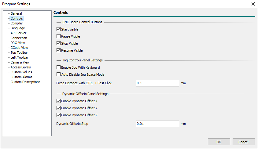
4.2.0.1 CNC Board Control Buttons
- Start Visible
- Defines if the Start button will be visible, or not, in the CNC Board Control Bar.
- Pause Visible
- Defines if the Pause button will be visible, or not, in the CNC Board Control Bar.
- Stop Visible
- Defines if the Stop button will be visible, or not, in the CNC Board Control Bar.
- Resume Visible
- Defines if the Resume button will be visible, or not, in the CNC Board Control Bar.
4.2.0.2 Jog Controls Panel Settings
- Enable Jog With Keyboard
- Enables the Jog control with the keyboard.
- With the Keyboard is possible to control X-Axis (
Left/Rightkeys), Y-Axis (Up/Downkeys), and Z-Axis (Page Up/Page Downkeys). - To do Jog with the keyboard the Jog Controls panel axis control must be visible and focused.
- To focus it click the mouse in the near zone or press the
F1key one or two times till the blue focus rectangle is shown.
- Auto Disable Jog Space Mode
- Enables the auto-disable of Jog Space Mode.
- When Jog movements are made with the Jog Controls panel and the
Jog Spacefield is checked, withAuto Disable Jog Space Modeactive, at end of the movement theJog Spacefield will be automatically disabled.
- Fixed Distance with CTRL + Fast Click
- Defines the fixed distance used when with the
CTLRkey pressed a fast key/left-mouse click is done in the desired axis movement. - When the
CTRLkey is pressed a fast click, below 500 ms of duration, moves the selected axis of programmed distance. - When the
CTRLkey is pressed a long long click, over 500 ms of duration, executes a normal Jog axis movement but with an initial delay of 500 ms required to detect if in the fixed distance mode.
4.2.0.3 Dynamic Offsets Panel Settings
Dynamic Offsets permit to add positive/negative offset to X/Y/Z-Axis during CNC working using the related floating panel.
A change of Dynamic Offsets is possible only with CNC in RUN State and in a range of +3/-3mm.
Don't use Dynamic Offsets during RTCP enabled movements (G43.4 or G43.7).
- Enable Dynamic Offset X
- Enables the Dynamic Offset feature for X-Axis.
- Enable Dynamic Offset Y
- Enables the Dynamic Offset feature for Y-Axis.
- Enable Dynamic Offset Z
- Enables the Dynamic Offset feature for Z-Axis.
- Dynamic Offsets Step
- Defines the minimum step (+ or -) of Dynamic Offsets value change.
4.3 Compiler
4.3.1 General
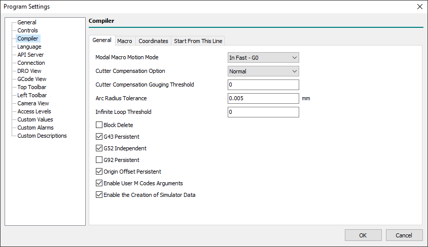
- Modal Macro Motion Mode
- Define the default motion mode used to perform the movements between two custom macro repetitions (Look at Modal Macro calls):
- In Fast - G0
- A fast movement with the
G0command will be performed.
- In Feed - G1
- A feed movement with the
G1command will be performed.
- In the G-Code Program/Macro/MDI, with the
G10 L100 P5800 V<value>command is possible to specify a different value from the default (#5800 = 0 → G0;#5800 = 1 → G1). - At the start of the G-Code Program/Macro/MDI, the default motion mode value will be always restored.
- Cutter Compensation Option
- Defines how the CNC Board will manage the Tool Cutter Compensation enabled with
G41/G41.1andG42/G42.1commands. - The available options are:
- NIST
- The default NIST mode.
- Easy Lead-In
- Delays the first movement of the entry move until the following line or arc is specified.
- When the second entry motion is specified it performs the entry move to a position tangent to the beginning of the second line or arc.
- This option works well with some CADs such as Fusion360 indeed no gouging errors are generated.
- Normal
- It is the only option that can handle concave corners and concave arcs.
- PS: For more info look at Tool Compensation Entry Options.
- Cutter Compensation Gouging Threshold
- Defines the cutter compensation gouging threshold applied to
G41/G41.1orG42/G42.1commands whenCutter Compensation Optionis set toNormal.
- Arc Radius Tolerance
- Defines the maximum accepted difference of the distance between the start point and the center of an arc and that between the end-point and the center of the arc before generating a compilation error.
- The value should be also equal to or higher than the greatest axes quantum movement (Axis Quantum = CNC Board axis
Measure / Pulses).
- Infinite Loop Threshold
- Defines how to manage a possible infinite loop in
WHILEcommands. - When the value is set to 0 means: Continue till the
WHILEexpression is satisfied or the user press theESCkey to abort the current compilation. - When the value is set > 1 means: Continue till the
WHILEexpression is satisfied or the user press theESCkey to abort the current compilation or then-valueloops are reached.
- Esample of an infinite loop:
- In this case the coder missed to increment #1 value (eg:
#1=[#1+1]) so the loop with Infinite Loop Threshold = 0 will continue to infinite. - For example with Infinite Loop Threshold = 10000, after 10000 loops the compiler will notice an error and stop compiling automatically.
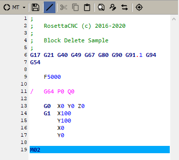
- Block Delete
- Enables Block Delete management.
- Block delete is used in a program by placing a forward slash (
/) at the beginning of the line. - It is a useful function that allows the operator to skip the blocks within the program.
- When the Block Delete option is enabled, and G-Code Editor Block Delete icon is active, all G-Code lines with
/will be disabled and not executed. - The G-Code located to the right of an enabled Block Delete is still subject to syntactic check even if the code execution will be skipped:
 |
- G43 Persistent
- Defines if
G43compensation is persistent in CNC Board at end of a G-Code Program/Macro/MDI execution.
- G52 Independent
- Defines if
G52is independent between changes of active WCS in a G-Code Program/Macro/MDI execution.
- G92 Persistent
- Defines if
G92offsets are persistent in the CNC Board at end of a G-Code Program/Macro/MDI execution.
- Origin Offset Persistent
- Defines if the changing of the selected World Coordinate System (WCS) made in the G-Code Program/Macro/MDI is kept at end of code execution:
- Checked
- At the start of the program execution, the current active WCS is used.
- At the end of the program execution, any changing of selected WCS with the
G54/G55/G56/G57/G58/G59.1/G59.2/G59.3commands will be kept. - In the case of the program stop, the current selected WCS is kept.
- Unchecked
- At the start of the program execution, the current active WCS is used.
- At the end of the program execution, any changing of selected WCS with the
G54/G55/G56/G57/G58/G59.1/G59.2/G59.3commands will be lost and WCS 1 (G54) is applied. - In the case of the program stop, the current selected WCS is kept.
The changes to any WCS origin offset values made with the G10 L2 Pp Xx Yy Zz Aa Bb Cc command are not affected by this parameter.
- Enable User M Code Arguments
- Define if the user-defined M macros will accept arguments, eg:
M201 A10 J-1.3.
- Enable the Creation of Simulator Data
- Defines if the creation of Simulator Data is enabled.
- Disabling Simulator Data will improve G-Code program compilation time and will reduce the memory used by the PC.
- In the 32-bit version of the control software, when the estimated execution time of the G-code exceeds 5 hours, the simulator data is automatically disabled.
4.3.2 Macro
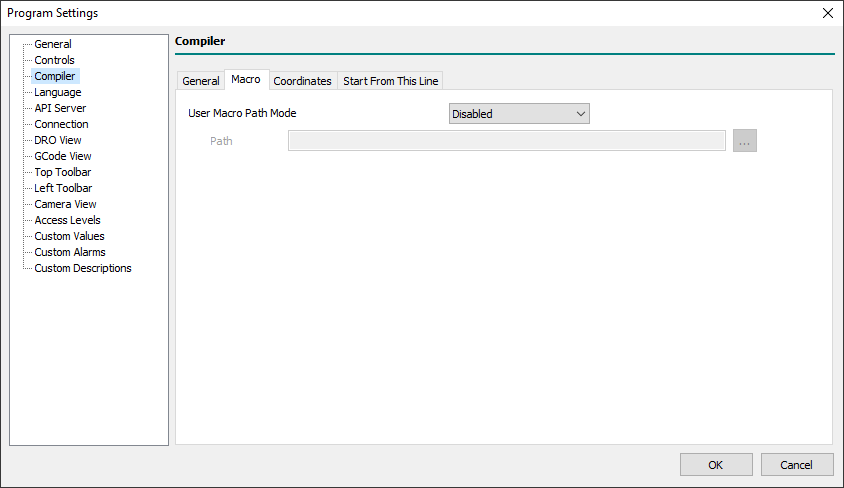
- User Macro Path Mode
- Two types of macros are available in the G-Code language: Machine Macros and User Macros.
- The Machine Macros are stored in the folder
%APPDATA%\RosettaCNC-1-\<machine>\macros. - To quickly reach the actual Machine Macros folder, you can use the “
File → Open Macro Folder” menu. - Machine Macros can be used to create new
G&Mcommands, provide well-defined CNC functions such as tool change, or subroutines that can be called up by number/name using theM98/G65/G66/CALLcommands. - User Macros can be ONLY used to create subprogram callables by name.
- User Macro Path is used ONLY if the subprogram is called with the prefix
/, eg:G65 P“/square_pocket.ngc” W100. H100. Z-40. R-5. T2. - The User Macro Path Mode allows this by choosing from the following options:
- Disabled
- The User Macro feature is disabled.
- GCode File Path
- The User Macros are searched in the same path as the currently opened G-Code Program.
- User Defined Path
- The User Macros are searched in the below-defined path.
- Path
- Defines the path where the User Macros are stored when the User Defined Path option was chosen.
4.3.3 Coordinates
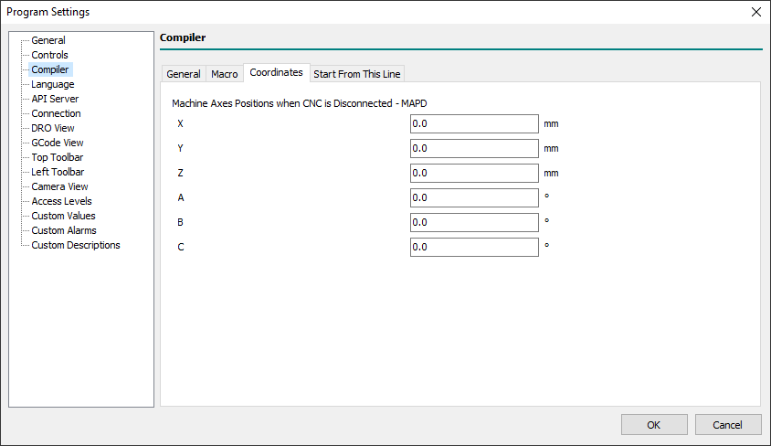
- Machine Axes Positions when CNC is Disconnected - MAPD
- Defines the machine axes positions used in Control software when not connected with a CNC Board.
- Typically these values are used how axes start points during G-Code simulation with internal software Simulator and without a CNC Board connected.
4.3.4 Start From This Line
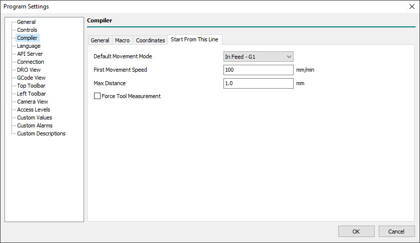
The System Macro restart.ngc manages all the activities necessary to START machining from a specific program line or to RESUME machining stopped with a STOP command from the last executed line or from one of your choice.
However, when the macro is not available, a series of minimal operations are performed.
The following parameters allow you to configure these operations.
- Default Movement Mode
- Defines how the CNC make the default movements to start Start/Restart from a line from:
- In Feed - G1:
default movements will use theG1command (feed movement). - In Fast - G0:
default movements will use theG0command (fast movement). - Handheld by the PLC:
default movements are managed by PLC internal strategy.
- First Movement Speed
- Defines the default movement speed when Default Movement Mode is set to In Feed - G1.
- Max Distance
- Defines the maximum accepted distance between the actual CNC position and the first CNC target position described in the G code.
- If the distance is greater than Maximum Distance, an error message will be displayed in the dialog box and no movement will be made.
- Force Tool Measurement
- If enabled, if the currently loaded tool is different from the required tool, the Tool Change procedure will be forced otherwise an error message will signal the case and no movement will be performed.
PS: This is a very poor way to manage a START/RESTART from a line. The use of the restart.ngc macro is the right way to get better management of that.
4.4 Language
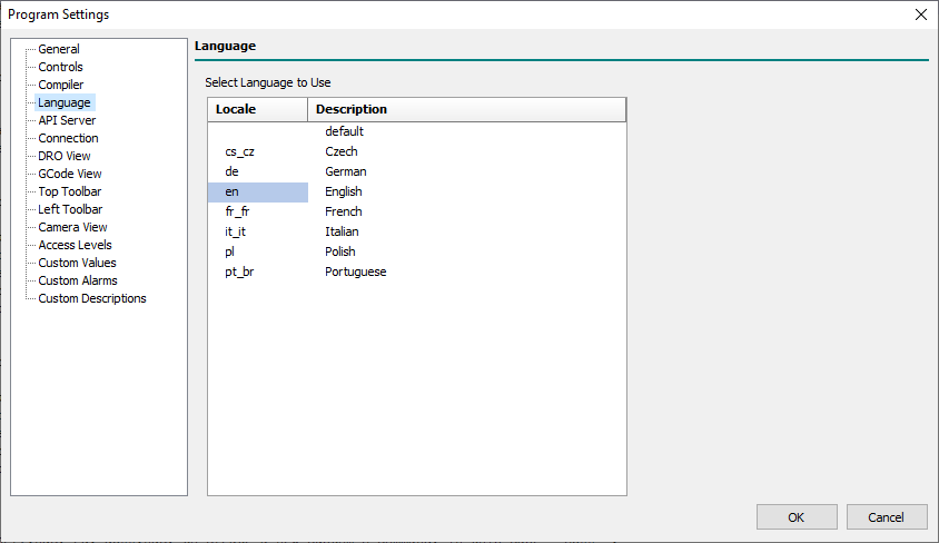
- Select Language to Use
- Permits to define the UI language to use choosing from available languages.
- Any change of current language requires a Control Software re-start to be fully applied.
PS: The Default item means “Use current computer default language, if present in the list, otherwise use the English language”.
4.5 API Server
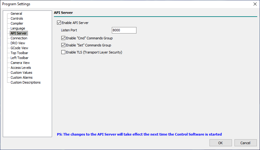
Through the API Server, the Control Software exports a part of its API which can be used with external client applications.
The API server is a TCP/IP Server listening on localhost with a communication protocol based on JSON Request/Response packets.
The API Server, if enabled, will be activated automatically when the Control Software is started.
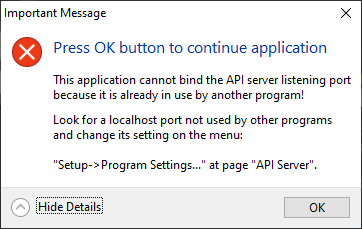
If, when starting the Control Software, the API Server Listening Port is found to be already in use, the following dialog will be displayed:
- Enable API Server
- Enabled the Control Software API Server.
- Listen Port
- Localhost Listening Port of the API Server.
- It can be any localhost port not already used in the range 0 to 65535.
- Enable “Cmd” Commands Group
- Enable the API Server “Cmd” commands group.
- Enable “Set” Commands Group
- Enable the API Server “Set” commands group.
- Enable “TLS” (Transport Layer Security)
- NOT YET IMPLEMENTED!
PS: The changes to the API Server will take effect the next time the Software Control is started.
4.6 Connection
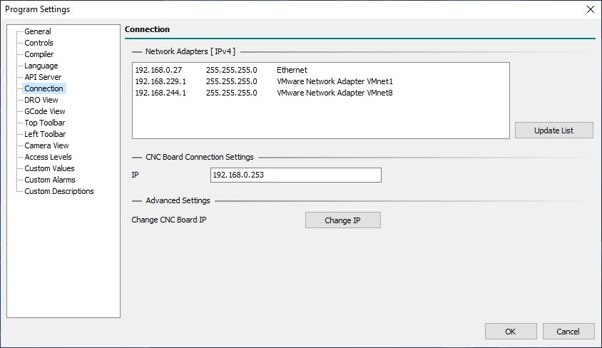
4.6.0.1 Network Adapters [IPv4]
This panel displays all the Network Adapters for the Internet Protocol version 4 that can be reached by the Control Software.
For each adapter in the list, the IP address, the NET MASK and the NET NAME are available.
- Update List
- Updates the list of Network Adapters.
- This is necessary if you change the Network configuration, eg: enabling a new LAN/WIFI connection.
4.6.0.2 CNC Board Connection Settings
- IP
- Defines the IP of the CNC Board to connect with.
4.6.0.3 Advanced Settings
- Change IP
- Permits to discovery and change the IP Settings of the CNC Boards connected in the Network.
- For more information, see the “How To: Change Board IP” page.
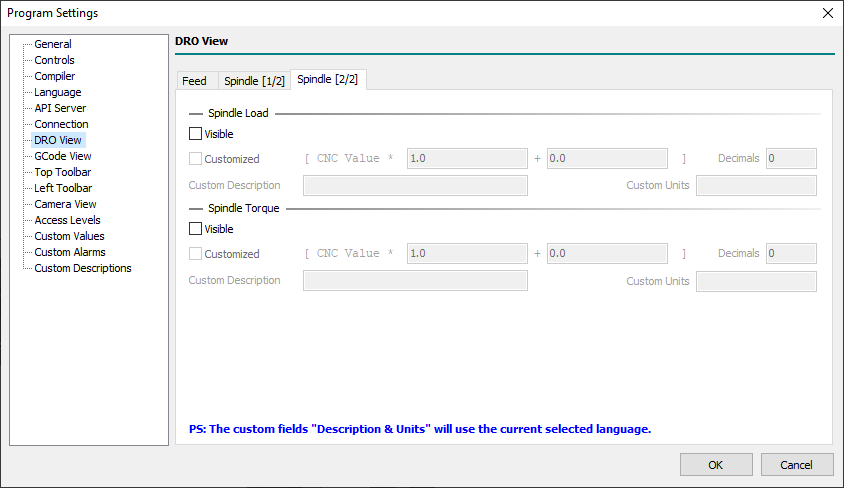
4.7 DRO View
4.7.1 Feed

4.7.2 Spindle [1/2]
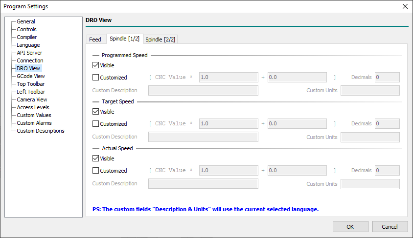
4.7.3 Spindle [2/2]
4.8 GCode View
4.8.1 General
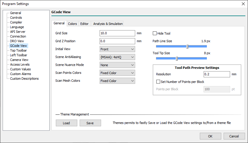
- Grid Size
- Defines the size of the Grid used to represent the XY-Axis area in the machine coordinates.
- Grid Z Position
- Defines the Z machine coordinate where the Grid will be placed.
- Is usual to place this value at the same Z-Axis Min Limit value.
- Initial View
- Defines the initial 3D view mode used as default when the Control Software is executed.
- The graphical engine will automatically fit the 3D scene objects to be all shown in the display.
- Choose one of the following values:
- Front
- The initial view will be on the front of the CNC.
- Back
- The initial view will be on the back of the CNC.
- Top
- The initial view will be at the top of the CNC.
- Bottom
- The initial view will be at the bottom of the CNC.
- Left
- The initial view will be on the left of the CNC.
- Right
- The initial view will be on the right of the CNC.
- ISO 1..9
- The initial view will be one of the ISO perspective modes.
- Custom View 1..4
- The initial view will be one of the ISO perspective custom modes.
- Scene AntiAliasing
- Defines the strength of Antialiasing filter applied by the graphical engine to 3D scene:
- Default
- Antialiasing disabled (will take the first available pixel format).
- None
- Antialiasing disabled (will take the first available pixel format).
- (MSAA): 2x
- Multisampled Antialiasing (MSAA): 2x.
- (MSAA): 2xHQ
- Multisample Antialiasing (MSAA): 2x High Quality.
- (MSAA): 4x
- Multisampled Antialiasing (MSAA): 4x.
- (MSAA): 4xHQ
- Multisampled Antialiasing (MSAA): 4x High Quality.
- (MSAA): 6x
- Multisampled Antialiasing (MSAA): 6x.
- (MSAA): 8x
- Multisampled Antialiasing (MSAA): 8x.
- (MSAA): 16x
- Multisampled Antialiasing (MSAA): 16x.
- (CSAA): 8x
- Coverage Sampled Antialiasing (CSAA): 8x.
- (CSAA): 8xHQ
- Coverage Sampled Antialiasing (CSAA): 8x High Quality.
- (CSAA): 16x
- Coverage Sampled Antialiasing (CSAA): 16x.
- (CSAA): 16xHQ
- Coverage Sampled Antialiasing (CSAA): 16x High Quality.
Default and None are similar but not the same.
Default does not touch the settings related to sample buffers of the OpenGL context from what defined in GPU Windows Settings.
None disables WGL_SAMPLE_BUFFERS_ARB and therefore the Anti-Aliasing management completely.
MSAA stays for Multi Sampled Antialiasing.
CSAA stays for Coverage Sampled Antialiasing.
Coverage Sampled Antialiasing (CSAA) is supported by NVIDIA cards (CSAA Tutorial)
- Scene Nuance Mode
- Xxx…
- Scan Points Colors
- Xxx…
- Scan Mesh Colors
- Xxx…
- Hide Tool
- Xxx…
- Path Line Size
- Xxx…
- Tool Tip Size
- Xxx…
4.8.1.1 Tool Path Preview Settings
- Resolution
- Xxx…
- Set Number of Points per Block
- Xxx…
- Points per Block
- Xxx…
4.8.1.2 Theme Management
- Load
- Permits to load a saved theme from a file.
- Save
- Permits to save the current theme in a file.
4.8.2 Colors
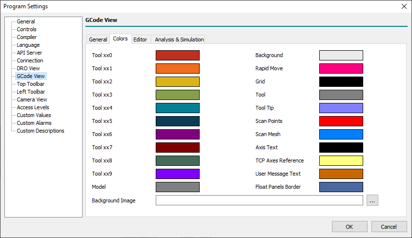
- Tool xx0..xx9
- Defines the colors assigned to Tools.
- The color assigned to the Tool depends on the last Tool digit number.
- Eg: Tool 1, 11, 21, .. share the same Tool color as 2, 22, 92, and so on.
- Model
- Defines the color of the G-Code program Model geometry.
- The G-Code program model is an STL file with the same G-Code program name, but extension STL, loaded when a G-Code program is loaded.
- Background
- Defines the 3D scene background color.
- This color is used when in the machine
customizepath is not available thebackground.pngbackground image. - If in machine
customizepath is available thebackground.pngimage the system will use the image instead of background color.
- Rapid Move
- Defines the color for toolpath G00 (rapid) movements.
- Grid
- Defines the color of the working area Grid.
- Tool
- Defines the color of the Tool Body.
- Tool Tip
- Defines the color of the Tool Tip Body.
- Scan Points
- Defines the color of Scan Points during Scanning 3D/Scanning Surface features.
- Scan Mesh
- Defines the
- Axis Text
- Defines the color of the Axis text in MCS origin.
- User Message Text
- Define the color of the User Message for the M109 command.
- Float Panels Border
- Defines the Float Panels border color for Jog/MDI/etc.
4.8.3 Editor
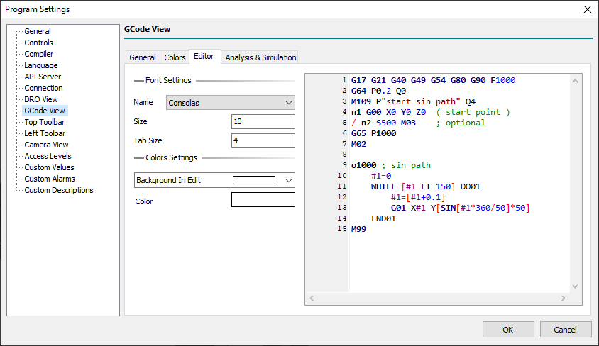
4.8.3.1 Font Settings
- Name
- Xxx…
- Size
- Xxx…
- Tab Size
- Xxx…
4.8.3.2 Color Settings Settings
- Color
- Xxx…
4.8.4 Analysis & Simulation
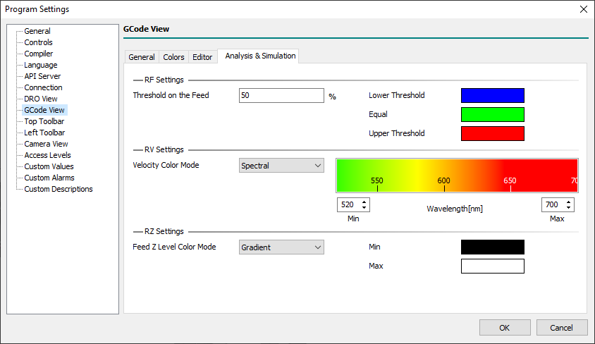
4.8.4.1 RF Settings
- Threshold on the Feed
- Xxx…
- Lower Threshold
- Xxx…
- Equal
- Xxx…
- Upper Threshold
- Xxx…
4.8.4.2 RV Settings
- Velocity Color Mode
- Xxx…
4.8.4.2.1 Spectral
- Min
- Xxx…
- Max
- Xxx…
4.8.4.2.2 Gradient
- Min
- Xxx…
- Max
- Xxx…
4.8.4.3 RZ Settings
- Feed Z Level Color Mode
- Xxx…
4.8.4.3.1 Spectral
- Min
- Xxx…
- Max
- Xxx…
4.8.4.3.2 Gradient
- Min
- Xxx…
- Max
- Xxx…
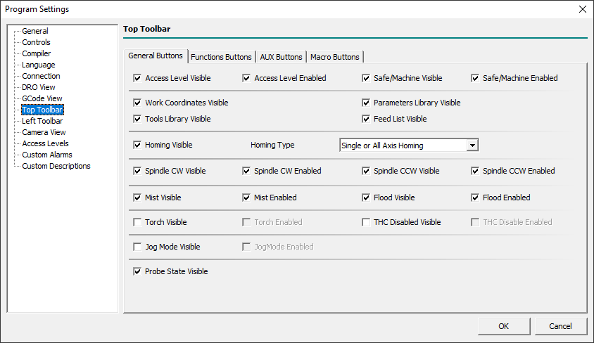
4.9 Top Toolbar View
Through this panel and related sheets, it is possible to set the visibility of buttons in the top toolbar.
4.9.1 General Buttons
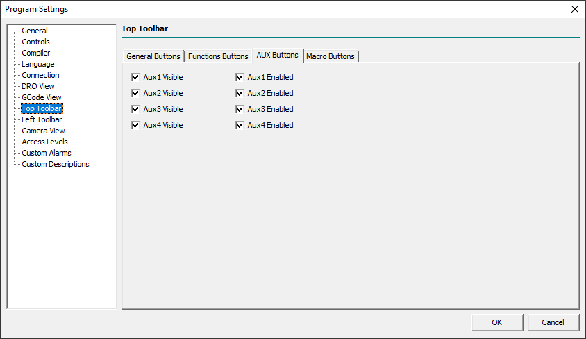
4.9.2 AUX Buttons
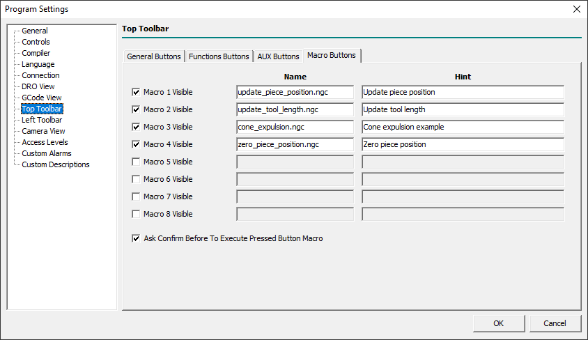
4.9.3 Macro Buttons
Through this sheet, it is possible to show and define the top toolbar macro button's actions.
4.10 Left Toolbar View
Through this panel, it is possible to set the visibility of some button in the left toolbar, also know as Machine Toolbar.
4.10.1 General Buttons
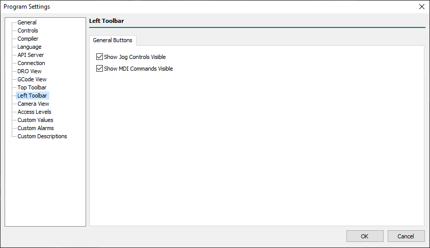
- Show Jog Controls Visible
- Defines the visibility of the left toolbar
Show Jog Controlsbutton. - When the button is not visible the
Jog Controlspanel can be yet shown/hidden pressing theF1key or using the related main menu item. - When the UI central area view is not in
Main View, showing or hiding theJog Controlspanel will automatically switch the view toMain View.
- Show MDI Commands Visible
- Defines the visibility of the left toolbar
Show MDI Commandsbutton. - When the button is not visible the
MDI Commandspanel can be yet shown/hidden pressing theF4key or using the related main menu item. - When the UI central area view is not in
Main View, showing or hiding theMDI Controlspanel will automatically switch the view toMain View.
4.11 Camera View
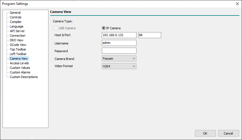
- Camera Type
- Defines the type of connected camera between “USB Camera” and “IP Camera”.
- At the moment ONLY IP cameras are supported.
- USB Camera
- Sets the Vision Engine to work with a USB Camera.
- IP Camera
- Sets the Vision Engine to work with an IP Camera.
- Host & Port
- Defines the Host & Port of the IP Camera.
- Username
- Defines the Username necessary to connect to the IP Camera internal server.
- Password
- Defines the Password necessary to connect to the IP Camera internal server.
- Camera Brand
- Defines the brand of IP Camera from one of supported brands:
- Undefined
- Foscam
- Panasonic
- Aviosys
- Smartec
- ACTi
- ArcVision
- Axis
- DLink
- Beward
- Genius
- Planet
- Samsung
- Trendnet
- Vivotek
- Video Format
- The Vision Engine support the following video formats:
- MJPEG
- H264
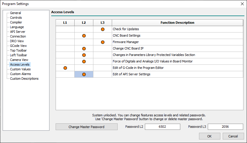
4.12 Access Levels
Through this panel, it is possible to restrict write access or disable access to some settings menus by binding everything to a password.
The system allows three access levels: L1, L2, and L3.
Level 1 is linked to the operations carried out by the machine operator.
This level does not have an associated password as it is active by default when the Control Software is started.
Level 2 could be associated with the maintenance technician of the machine who periodically may need to intervene in some aspects of the same.
Level 3 is usually the level associated with the manufacturer who is the only one who can intervene on delicate parts such as axis settings, or the firmware and software update functions.
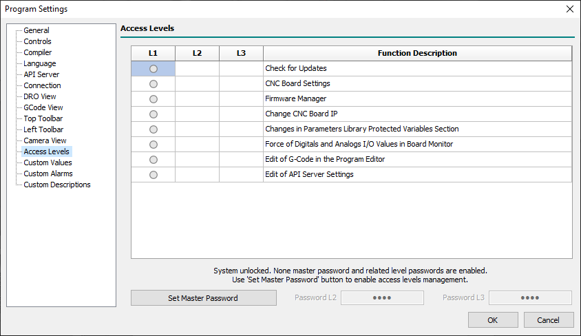
- Access Levels Table
- The table shows the functions of the Control Software that can be bound by an access level.
- The orange DOT symbol indicates to which access level every single function is associated.
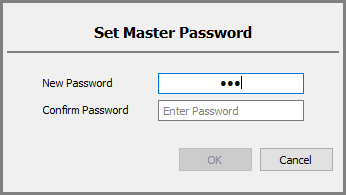
- Set Master Password
- In order to activate the system of access levels, the manufacturer of the machine must introduce a Master Key which is necessary so that it is possible to associate the functions to the various levels.
- By default, after installation, the master access key is not set and the functions are available to anyone as the access level management is not configured.
- The master key must be brought back and kept in order to be able to configure the access levels at any time.
- If the master password has never been entered, a double confirmation will be requested before accepting it:
- If a master password has already been entered and you want to change it, you must first enter the old password followed by the double-entry of the new one:
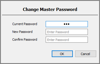
- A new password consisting of an empty string means that you want to disable the level access system.
- Password L2
- Defines the password for access level L2.
- The password can be numeric or alphanumeric.
- The password must be different from the master password or other level passwords.
- Password L3
- Defines the password for access level L3.
- The password can be numeric or alphanumeric.
- The password must be different from the master password or other level passwords.
A practical example of a typical configuration:
4.13 Custom Alarms
4.13.1 Alarms [ From Inputs ]
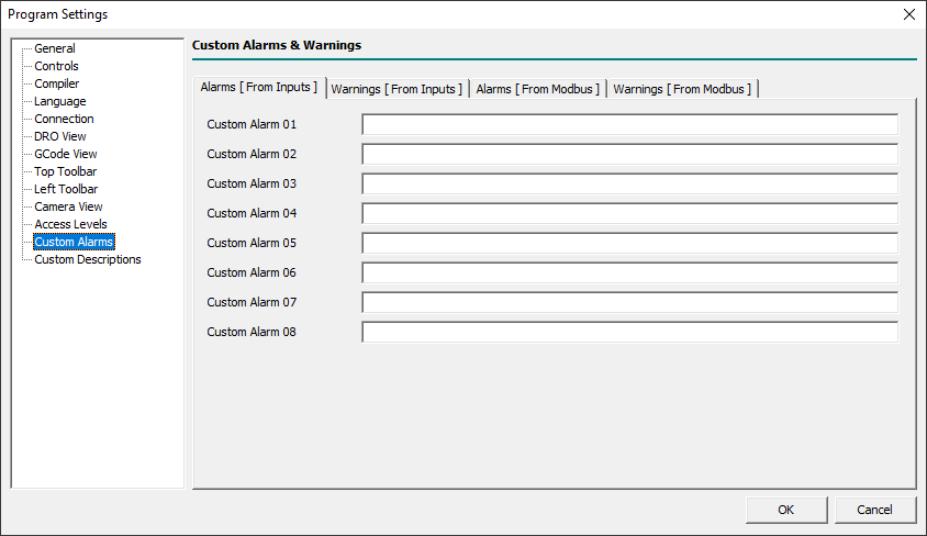
- Custom Alarm 01..08
- Xxx…
4.13.2 Warnings [ From Inputs ]
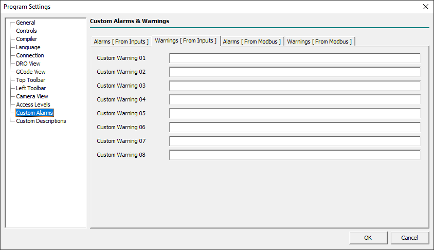
- Custom Warning 01..08
- Xxx…
4.13.3 Alarms [ From Modbus ]
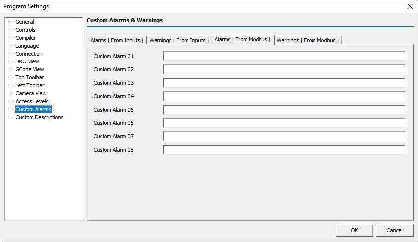
- Custom Alarm 01..08
- Xxx…
4.13.4 Warnings [ From Modbus ]

- Custom Warning 01..08
- Xxx…
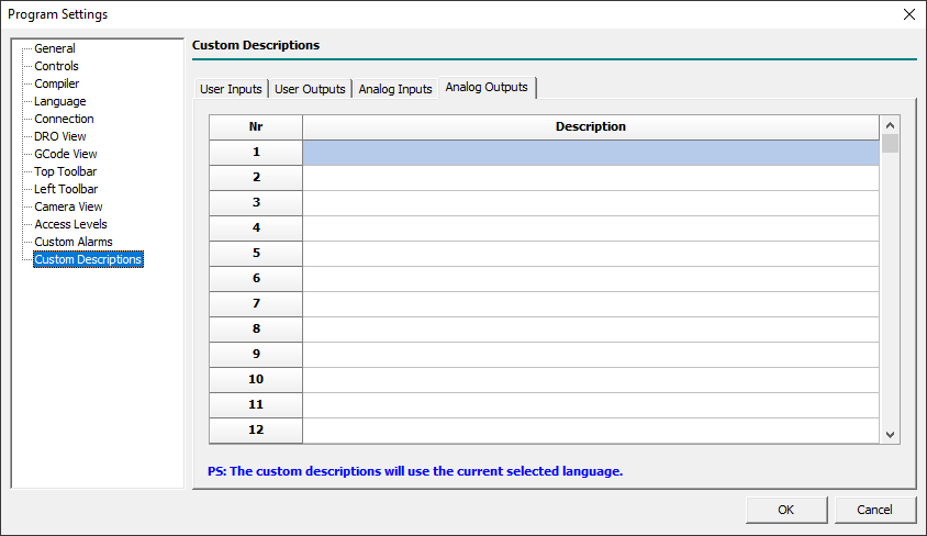
4.14 Custom Descriptions
Through this panel and related sheets, it is possible to define the custom descriptions for user inputs/outputs and analog inputs/outputs.
For the custom descriptions, only chars from the ANSI chars set are usable.
Every language supported by Control Software will have its messages so if the English language is active the showed/entered messages in the grid will be for English.
To Enter the descriptions for a different language select what in the Language panel then enter related text in the grid.
All messages are stored in the external file rosettacnc.ini, of the current machine, and they could be also edited with an external editor in the ANSI char format.
The custom descriptions will be used and shown in the Board Monitor panel reachable with the menu Setup→Board Monitor.. when the Control Software is connected with a CNC Board:
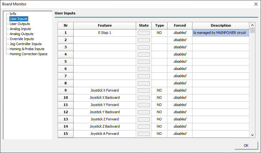
The Board Monitor is enabled to permits direct editing of the description fields in the currently active language.
4.14.1 User Inputs

This sheet permits editing of the user inputs custom descriptions.
The field Nr corresponds to the user input number (eg: 1 = user input 1).
The field Description will contain the custom description text in the currently active language.
4.14.2 User Outputs

4.14.3 Analog Inputs

4.14.4 Analog Outpus
6. Board Settings
Some of the following CNC Board Settings are also accessible in the G-Code programming language via the corresponding read-only Named Parameters.
When available, the Named Parameter will be visible next to the parameter description, e.g.:
- Machine Type - [
#<cnc.machine_type>]
All CNC Board Settings, and related named parameters, will be exclusively in the Metric Measurement System.
6.1 General
The General panel contains the generic CNC settings.

- Condition that Enables the Update of Settings
- The OK button of the Board Settings panel will be always enabled with Control Software non-connected to the CNC Board.
- When the Control Software is connected to the CNC Board, the status of the OK button depends on the following settings:
- Only when axes are stopped
- The OK button is enabled when there are no movements in execution (CNC in
IDLE/ALARMstate).
- Only when axes are disabled
- The OK button is enabled when Board State is in
WAIT MAIN POWER. - To enter in
WAIT MAIN POWERis necessary to have assigned a digital input to the feature Main Power Input on the Inputs sheet.
- Action To Do if Disconnected in RUN State
- When the connection between the PC and the CNC is interrupted a timeout timer of 4 seconds starts.
- At the end of that, if the CNC is in the RUN state, it automatically switches the CNC to one of the following new states:
- Go To PAUSE State
- The CNC enters in
PAUSEstate.
- Go To ALARM State
- The CNC enters in
ALARMstate.
6.1.0.1 General Settings for Homing
- Velocity Divider
- This is the parameter that defines the ratio between the homing velocity (used when an axis starts the Homing sensor search movements)
- and the final homing switch search movement.
- Example:
- If you set Home Velocity Divider to 10 and the X-Axis Homing Velocity is 6000mm/min, the Homing switch search speed will be 600mm/min.
- Allowed Commands without Homing Done
- Xxx.
6.1.0.2 Withdraw/Retract Tool at Stop Settings
- Withdraw/Retract Tool feature permits to define what CNC has to do when a STOP action is requested to CNC (eg: STOP user input becomes ACTIVE).
- It permits to extract the tool from the stock of a desired distance and velocity.
- After Withdraw/Retract Tool action CNC will execute the STOP action and will enter in
IDLEstate.
- TAKE CARE: If the CNC has not searched for the reference point (homing), the CNC will not carry out the
Withdraw/Retract Toolprocedure.
- Mode
- With the
Modefield is possible to define what type of Withdraw/Retract Tool action will be done:- Disabled
- At the
STOPrequest no Withdraw/Retract action is executed, and the CNC job stops immediately.
- Normal
- At the
STOPrequest the Z-axis moves UP of space defined in theDistancefield. - The requested
Distancewill be limited to Z-axisMax Limitvalue. - This is the common option for Kinematics: Trivial, Independent Rotational Axes, Rotary Table A/C, and Rotary Table B/C.
- Along Tool Direction
- At the
STOPrequest the tool will be extracted following the tool direction vector of measure defined in theDistancefield. - The requested
Distancewill be limited to axesMax Limitvalues. - This is the common option for Kinematics: Tilting Spindle A/C.
- Distance
- The parameter defines the distance from the current tool position to do to extract the tool from stock.
- Velocity
- The parameter defines the percentage of axis/axes max interpolation velocity to be used during the extraction of the tool from stock.
6.2 Axes
The Axes panel contains the CNC Board settings for movement axes.
The panel is subdivided into a variable number of sheets that vary according to what is set in the parameters Machine Type, Kinematics Model, and Axis Type.

6.2.1 Machine
Before beginning to set the axes parameters it is necessary to define the machine configuration.
In this sheet are collected all main settings required to do that.
- Machine Type - [
#<cnc.machine_type>]
- This is the parameter that defines the machine type.
- At the moment the field is disabled and fixed to Mill which means: Mill and Mill/Turn machine.
- Kinematics Model - [
#<cnc.kinematics_model>]
- The CNC Board supports a fixed set of Kinematics to cover all common Mill and Mill/Turn configurations:
- Trivial
- There is a 1:1 correspondence between joints and axes. Most standard milling machines and lathes use the trivial Kinematics model.
- The simplest machines are those in which each joint is placed along with one of the Cartesian axes.
- The toolpath graphic representation will be rendered according to axis positions.
- The Virtual Machine Engine does not support the Trivial model so the VM Parts Geometries will not follow the movements of axes.
- Independent Rotational Axes
- With this Kinematics model, the toolpath will be rendered according to Rotational Axes settings.
- Rotational axes set to
Free Rotary Axiswill not be rendered in toolpath graphic and uses as a linear axis with degrees as um. - Rotational axes set to
Rotary Axis for Tablewill concur to toolpath graphic representation according toKinematicssheet settings. - The Virtual Machine Engine will fully support the VM Parts Geometries following the movements of axes.
- Rotary Table A/C
- Xxx.
- With this Kinematics the Master Rotary Axis is A (turn around X-Axis) and the Slave Rotary Axis is C.
- The Virtual Machine Engine will fully support the VM Parts Geometries following the movements of axes.
- Rotary Table B/C
- Xxx.
- With this Kinematics the Master Rotary Axis is B (turn around Y-Axis) and the Slave Rotary Axis is C.
- The Virtual Machine Engine will fully support the VM Parts Geometries following the movements of axes.
- Tilting Head C/A
- Xxx.
- With this Kinematics the Master Rotary Axis is C and the Slave Rotary Axis is A.
- The Virtual Machine Engine will fully support the VM Parts Geometries following the movements of axes.
- Tilting Head A/B
- Xxx.
- With this Kinematics the Master Rotary Axis is A and the Slave Rotary Axis is B.
- The Virtual Machine Engine will fully support the VM Parts Geometries following the movements of axes.
- Axis Type - [
#<cnc.x.type>..#<cnc.w.type>]
- Depending on the kinematic model chosen, each axis can be set to a range of possible axis types:
- Disabled - [
#<axis.type.disabled>]
- The Axis is disabled and can't be used in G-Code.
- If a disabled Axis is used in the G-Code Program, Macros, or MDI, a compile error will be raised.
- Linear Axis - [
#<axis.type.linear>]
- The Axis is of linear type.
- Free Rotary Axis - [
#<axis.type.rotary_free>]
- The Axis is of the free rotary type.
- A free rotary Axis doesn't have any Kinematics management and its behavior is very close to Liner Axis but use the degree as space units.
- Rotary Axis for Head - [
#<axis.type.rotary_head>]
- Xxx.
- Rotary Axis for Table - [
#<axis.type.rotary_table>]
- Xxx.
- Slave Axis of Gantry 1 - [
#<axis.type.gantry_1>]
- Xxx.
- Slave Axis of Gantry 2 - [
#<axis.type.gantry_2>]
- Xxx.
6.2.1.1 Axes Types for Kinematics Type Mill (Mill/Turn)
- At least two linear axes must be enabled to permits G-Code compilation.
- Axes Types fields in Bold are pre-defined depending on selected Kinematics.
Follow description of Axes Types available with Kinematics of Mill (Mill/Turn) Machine Type:
| Mill Kinematics Type | Axes Types |
|---|---|
| Trivial |
|
| Independent Rotational Axes |
|
| Rotary Table AC |
|
| Rotary Table BC |
|
| Tilting Spindle AC |
|
6.2.2 X .. W

- This panel is the same for axis X to W.
- Available named parameters are reported for X-axis (eg:
#<cnc.x.min_lim>) but are available for every axis from X to W, just change the axis letter.
- Pulse
- Define the impulses necessary to obtain a complete revolution of the motor.
- For steppers motors, this parameter must include the micro-steps so if you have a 200 pulse motor with 8 micro-steps in the driver, you need to set it to 1600.
- For brushless motors, you have to set it to the same pulses set in the driver for a complete revolution.
- Measure
- It is the movement made by the axis with a complete revolution of the motor.
- Max Velocity - [
#<cnc.x.max_vel>] - Defines the maximum velocity value of motor in mm/min and is used with the rapid movements ( Eg:
G00). - It is also the base velocity used to get other CNC movement velocities, as for Jog, Homing, etc.
- Acceleration - [
#<cnc.x.acc>] - Defines the rate of change of interpolated velocity in time and is expressed in mm/s².
- Interpolation acceleration and deceleration share the same value in axis settings.
- The acceleration can be influenced by override when
Override Modeis set toSpeed and Space. - With the
G104command is possible to define a different acceleration/deceleration value for the interpolated point.
- Jog Acceleration
- Defines the rate of change of axis velocity in time during a Jog action acceleration and is expressed in mm/s².
- Jog Deceleration
- Defines the rate of change of axis velocity in time during a Jog action deceleration and is expressed in mm/s².
- Min Limit - [
#<cnc.x.min_lim>]
- Defines the minimum boundary of the axis in mm.
- Max Limit - [
#<cnc.x.max_lim>]
- Defines the maximum boundary of the axis in mm.
- Acceleration Time
- Shows the time required to reach the axis maximum velocity starting from 0.
- Max Frequency
- Shows the maximum frequency used to reach the axis maximum velocity.
- This value can help to understand if the chosen axis configuration is compatible with CNC Board or Axis Driver specifications.
- During the CNC Board order is necessary to choose the maximum STEP/DIR frequency of axes pulse generator between 125/250/500/1000 Hz.
- Every STEP/DIR driver has a maximum frequency acceptable for STEP/DIR signal that must be equal or major than the
Max Frequencyvalue.
- Homing: Mode
- Define the axis homing modality (Home Search chapter).
- Every axis can have a different homing mode choosing from:
- Disabled
- In this mode, nothing is done when the Homing Search procedure is started.
- The axis position already appears black to indicate that the machine position is synchronized.
- No Movement
- In this mode, no movement is commanded to the axis when the Homing Search procedure is started.
- The axis machine position is directly loaded with the parameter
Homing: Offsetvalue. - This mode is used when the CNC has no Homing Sensors.
- Thus the Homing Search procedure is started when the operator manually jogs the axes to the machine reference point.
- Rising Edge
- In this mode, the Homing Search procedure is:
- 1] The axis moves to the selected direction in
Homing: DirectionatHoming: Velocityfeed until the axis meets the Homing sensor. - 2] Then axis reverse direction and decrease velocity by a factor defined by the general parameter
Velocity Divider. - 3] When the Homing sensor escapes, the
Homing: Offsetvalue will be loaded into the axis machine position. - 4] Finally the axis is moved to
Homing: Final Position.
- Falling Edge
- This mode is very similar to Rising Edge but when the Homing sensor escapes, the axis will reverse direction again and load the machine position when the axis meets the homing sensor.
- This mode is used if the Homing sensor has a higher precision in the switching edge opposite to that defined in Rising Edge mode.
- Use of this modality in combination with the
Homing: Index Inputis not permitted.
- Absolute
- This mode is used in the EtherCAT servo drive with an absolute encoder.
- No movement is commanded to the axis when the Homing Search procedure is started.
- The axis machine position will be loaded with the resulting value from the Servodrive position minus
Homing: Offsetvalue.
- Absolute with Final Position
- Is the same as Absolute mode but after the load of the machine position the axis is moved to
Homing: Final Position.
- Pushing
- Xxx.
- Pushing Switch Rising Edge
- Xxx.
- Pushing Switch Falling Edge
- Xxx.
- Homing: Sequence
- Define the homing sequence during a Homing All axes action.
- When a “Homing All Axes” action is required at first all axes with
Sequence= 1 will be referenced. - After will follow all axes with
Sequence= 2 and so on tillSequence= 6. - To improve the axis homing quality is a good choice to have only one axis in the movement at a time.
- Homing: Direction
- Xxx.
- Homing: Index Input
- Xxx.
- Homing: Pushing Output
- Xxx.
- Homing: Pushing Position
- Xxx.
- Homing: Offset
- Xxx.
- Homing: Final Position
- Xxx.
- Homing: Velocity
- Xxx.
- Homing: Acceleration
- Xxx.
- Homing: Deceleration
- Xxx.
- Homing: Deceleration Space
- Xxx.
- Dir Hold time
- Defines the minimum HOLD time, in nanoseconds, of DIR signal in the STEP/DIR generator.
- The default value of 20000 should work for 99.99% of common drivers and don't should be modified.
- The value is however modifiable for very low-quality motor drivers where required minimum time is higher.
- Negate DIR Signal
- Permits to invert DIR signal value and so reverse motor direction.
- This can be useful when the motor movements result inverted in direction to avoid to change cabling.
- Negate STEP Signal
- Permits to invert STEP signal.
6.2.3 Kinematics

- Use this sheet to configure machine kinematics parameters.
- The proposed fields change and reflect the Kinematics Model and Axis Type defined in Axes→Machine sheet.
- Motion Mode
- Xxx…
- Convention
- Xxx…
- Wrapped Rotary
- Xxx…
- Parallel To
- Xxx…
- Kinematics parameters table
- Xxx…
6.2.4 Extra

- Cotangency Threshold
- Xxx…
- Cornering Minimum Speed
- Xxx…
- Cornering Acceleration Override
- Xxx…
- Blending Acceleration Override
- Xxx…
- Extra Override on Fast with Kinematics
- Xxx…
- Allow Immediate Direction Change
- Xxx…
- Enable Rotary Feed Handling
- Xxx…
6.3 Gantries

6.4 Spindle
6.4.1 General

- Spindle Mode
- Defines the Spindle type from:
- Normal
- The spindle has only a one-speed range.
- With Automatic Change Ranges
- The spindle system has two or more speed ranges.
- Spindle Analog Output Mode
- Defines the Spindle analog output setting mode:
- Mode A: CW+ and CCW +
- The spindle analog output for clockwise (CW) rotations will use values between 0 to +10V.
- The spindle analog output for counter-clockwise (CCW) rotations will use values between 0 to +10V.
- For a unidirectional spindle, a digital output must be configured to indicate the spindle driver-enabled status.
- For a bidirectional spindle, two digital outputs must be configured to indicate the spindle driver-enabled status and direction of rotation.
- Mode B: CW+ and CCW -
- The spindle analog output for clockwise (CW) rotations will use values between 0 to +10V.
- The spindle analog output for counter-clockwise (CCW) rotations will use values between 0 to -10V.
- For a unidirectional spindle, a digital output must be configured to indicate the spindle driver-enabled status.
- For a bidirectional spindle, two digital outputs must be configured to indicate the spindle driver-enabled status.
6.4.2 Normal

- Spindle Max Speed
- Defines the maximum speed of the spindle in rpm.
- The entered value corresponds to place 10v in spindle analogic output.
- For e.g. with the field set to 18000 rpm:
- Executing the G-Code
S18000 M03
- The spindle analog output will be placed to 10V (maximum speed) in the clockwise rotation mode.
- Executing the G-Code
S9000 M03
- The spindle analog output will be placed to 5V (half speed) in the clockwise rotation mode.
- Executing a G-Code with an higher RPM value than possible
S30000 M03
- The spindle analog output will be placed to 10V (maximum speed) in the clockwise rotation mode BUT the spindle will reach only its maximum speed.
- Spindle Start Time
- Defines the settling time of the spindle required to reach the programmed speed.
- While waiting for spindle adjustment, the execution of the next block is put on hold.
- The timing starts when:
- The spindle operating status is changed with the
M03/M04/M05commands. - The spindle speed in use is changed with the 'S' command with the spindle on.
- NOTE
- If the spindle supports the feature
At Speed InputorZero Speed Inputthe following behaviors table is applied:
| Spindle State | At Speed Input | Zero Speed Input | Description |
|---|---|---|---|
From M05 to M03/M04 | NO | Spindle Start Time is used to wait for spindle speed settle. |
|
From M05 to M03/M04 | YES | At Speed Input is used to wait for spindle speed settle. |
|
From ON to OFF (M05) | NO | Spindle Start Time is used to wait for spindle speed settle. |
|
From ON to OFF (M05) | YES | Zero Speed Input is used to wait for spindle speed settle. |
|
Switch from M03 or M04 or M04 to M03 |
6.4.3 Feature

- Spindle CW Input
- Defines the user input to manually start the spindle in the clockwise direction.
- This input is enabled only in CNC Board
IDLEstate. - The input work in TOGGLE mode when
Spindle Stop Inputis not defined.
- Spindle CCW Input
- Defines the user input to manually start the spindle in the count clockwise direction.
- This input is enabled only in CNC Board
IDLEstate.
- Spindle Stop Input
- Defines the user input to manually stop the spindle.
- At Speed Input Input
- Xxx.
- Zero Speed Input
- Xxx.
- Spindle Not Ready Input
- Xxx.
- Spindle S1
- The Tool-holder cone is attached correctly.
- Spindle S2
- The Collet is open.
- Spindle S4 (Optional).
- HSK cone is locked in the correct position.
- Spindle S5 (Optional).
- The Piston is in the upper position.
- If your ATC spindle provides standard
S1..S5output signals you can enable the CNC Board Spindle Control Signals Check management. - The Spindle Control Signals Check (SCSC) management is disabled if Spindle is OFF (
M05) or during tool change in G-Code inner aM107toM108block. - For the base check
S1andS2are mandatory. - In some ATC spindles, the signal
S4orS5is not available, so these checks are optional, and relatedS4/S5fields must be set toNone.
Status modes of the spindle and corresponding outputs:
| STATE | S1 | S2 | S5 | ACTION |
|---|---|---|---|---|
| Tool-Holder blocked correctly | ON | OFF | ON | It is allowed machining. |
| Collect closed but tool-holder absent | OFF | OFF | ON | The Tool-holder is not engaged correctly. It is not allowed machining. The electrospindle cannot run. |
| Collect open | OFF | ON | OFF | The tool-holder is released. |
6.4.4 Feedback

Starting from firmware 1.58 Spindle Feedback is available. Spindle speed can be read back by a digital sensor (Tachometer) or Analog input.
- Tachometer
- Read the frequency of the digital signal connected to TACHO terminal. Frequency is read in 0.01 Hz resolution.
- For example, if you apply a 1Hz signal, control software prints 100rpm as the spindle speed.
- To scale this value for the spindle real speed, use the Spindle Tachometer Factor (from 0.001 to 20).
- Also if you need more scaling factor please visit
Program Settings→ DRO View → Spindle 1/2 → Target Speed
- Analog inputs
- Analog inputs can read Speed, motor current (Load) and Torque.
- Set Analog source and PLC parameters from 50 to 64 to scale and filter the source value.
To show spindle feedback data in control software please visit Program Settings→ DRO View panel.
Actually, there is no check on spindle feedback to generate alarms or warnings.
6.5 Overrides
6.5.1 General

- Override Mode
- This is the main setting that defines how CNC Override System has to work with interpolated movements:
- Speed
- With Override Mode set to Speed the override control has effects only on target speed.
- Speed and Space
- With Override Mode set to Speed and Space mode, the override control has effects on target speed and acceleration/deceleration space.
- IMPORTANT NOTE:
- While validating the Board settings, the Override Mode will automatically be changed to Speed if the Feed → Max Override value is greater than 100%.

6.5.2 Jog/Spindle/Fast/Feed/Feed Custom 1/Feed Custom 2/Plasma Power/Plasma Voltage

This panel is the same for Jog/Spindle/Fast/Feed/Feed Custom 1/Feed Custom 2 features.
The overrides are active depending by M48/M49/M50/M51 commands following this table:
| Command | Spindle | Fast | Feed | Feed Custom 1 | Feed Custom 2 |
|---|---|---|---|---|---|
M48 | ON | ON | ON | off | off |
M49 | off | off | off | off | off |
M50 | unchanged | ON | ON | off | off |
M50 P0 | unchanged | off | off | off | off |
M50 P1 | unchanged | ON | ON | off | off |
M50 P2 | unchanged | off | off | ON | off |
M50 P3 | unchanged | off | off | off | ON |
M51 | ON | unchanged | unchanged | unchanged | unchanged |
M51 P0 | off | unchanged | unchanged | unchanged | unchanged |
M51 P1 | ON | unchanged | unchanged | unchanged | unchanged |
- Override Control Mode
- Every feature can have a different Override Control Mode choosing from:
- None
- Override Control is disabled and the related OVR value is set at 100%.
- MPG 1..16
- Override Control is managed by the chosen MPG Input source.
- Analog 1..16
- Override Control is managed by the chosen Analog Input source.
- Only at PC
- Override Control is managed with a PC Track Bar.
- Min Override
- Defines the minimum override value.
- Max Override
- Defines the maximum override value.
- The maximum accepted value changes according to the destination of the override:
- 100% for Jog and Fast.
- 300% for Spindle, Feed, Feed Custom 1, and Feed Custom 2.
- Analog Lower Threshold
- Defines the analog lower threshold associated with Min Override's value.
- When analogic input reaches or goes below this value the resulting override value will be placed to Min Override.
- Analog Upper Threshold
- Defines the analog upper threshold associated with Max Override's value.
- When analogic input reaches or goes upper this value the resulting override value will be placed to Max Override.
- MPG Input 1..16
- Defines the MPG Input source for override control.
- Analog Input 1..16
- Defines the Analog Input source for override control.
6.5.2.1 Override Inputs
- MPG Input 1..16
- If Control Software is connected to a CNC Board, these fields will show the current values of connected MPG Inputs to help the end-user to choose the right one.
- Analog Input 1..16
- If Control Software is connected to a CNC Board, these fields will show the current values of connected Analog Inputs to help the end-user to choose the right one.
6.6 Jog Controller
6.6.1 General

- Jog Controller Type
- Defines the Jog Controller Type between:
- None
- None Jog Controller is used.
- Handwheel A/B
- Single Joystick
- A Single Joystick is connected with the CNC Board in the Handwheel dedicated connector.
- Multiple Joystick
- A Multiple Joystick is connected with the CNC Board in the Handwheel dedicated connector.
- Enable Jog Controller Zero
- When the
Jog Controller Typeparameter is set toHandwheel A, the Handwheel Enable Button can be used to set to zero the program position of the selected axis. - To do that is necessary to:
- Check if CNC Board is in the
IDLEstate. - Select the desired axis with the Handwheel Axis Selector.
- Press three times the Handwheel Enable Button in the time defined in the
Jog Controller Zero Timeparameter.
- If all was well done the selected axis program position will be set to zero value and the axis machine position will be placed in the active WCS of the axis.
- Jog Controller Zero Time
- Defines the check time for the
Enable Jog Controller Zeroprocedure.
- Handwheel Pulses per Revolution
- Defines the number of pulses per revolution supplied by the handwheel MPG so that one revolution of the handwheel will move the axis of the desired measurement in x1/x10/x100.
- Normally if the handwheel declares 100 PPR the CNC, reading the 4 fronts of the A/B phases will count 400 (x4) so 400 should be introduced in this field.
- In CNCs for precision mechanics, with an MPG of 100 PPR, it is customary to enter a value of 4000 so that an MPG rotation in x1 gives a displacement of 0.1mm.
- Handwheel Velocity
- Xxx…
- Jog Default Mode
- Xxx…
- Maximum Interpolated Jog Velocity
- Xxx…
- Jog Mode Selector
- Xxx…
6.6.2 Joystick - Backward

- Joystick X..W Input
- Xxx…
6.6.3 Joystick - Forward

- Joystick X..W Input
- Xxx…
6.7 Inputs
6.7.1 Feature

- Main Power Input
- Xxx…
- E Stop 1 Input
- Xxx…
- E Stop 2 Input
- Xxx…
- Limit Input
- Xxx…
- Pause Input
- Define the User Input for the machining Pause feature.
- The Pause Input is checked only when the CNC Board is executing a G-Code program/macro/MDI e CNC Board is or must enter in
RUNstate. - The input works on the level therefore as long as the input is active and the CNC board is executing a G-Code program/macro/MDI it remains in the “PAUSE” state.
- The CNC Board will back to the
RUNstate when User Input will be deactivated. - When Pause Input is active and the operator run a new G-Code program/macro/MDI the CNC Board automatically changes from
IDLEtoPAUSEstate.
- Start Input
- Xxx…
- Stop Input
- Xxx…
- Optional Stop Input - [ for M01 ]
- Xxx…
- Continue Input
- Xxx…
- Resume Input
- Xxx…
- Alarm Reset Input
- Xxx…
6.7.2 Probe

6.7.3 Homing

6.7.4 Drivers

6.7.5 Macro

6.7.6 Door Security

6.8 Outputs
6.8.1 M-Codes

- M3 (Spindle On CW)
- Defines the User Output for spindle ON in the clockwise direction.
- M4 (Spindle On CCW)
- Defines the User Output used for spindle ON in the counter-clockwise direction.
- AUX Outputs
- Defines the association between G-Code AUX outputs and the User Outputs.
- To modify the state of a User Output between G-Code there are two commands:
M62 P<aux_number>(Turn AUX Output ON) andM63 P<aux_number>(Turn AUX Output OFF). - The available G-Code AUX Outputs are 32 and can be mapped to actual User Output using this table.
- To be simple in G-Code reading, when possible, try to keep a 1:1 correspondence between AUX and User Output number, so AUX 1 corresponds to User Output 1.
- However, you can also say that AUX 3 is User Output 1 and a
M62 P3will put ON the User Output 1.
6.8.2 Feature

- PC Is Connected
- Specified user output is
ONwhen a connection between PC Control Software and CNC is established. - When connection falls the output will be
ONfor a timeout time of 4 seconds during that buffered program will continue to work. - If the connection will be restored before timeout finishes the system will continue to work normally.
- Tool Change in Progress
- The specified user output will be
ONduring a tool change procedure invoked with aM06command. - When in the G-Code a
M6is called, the macrotool_change.ngc, with tool change program code, is executed. - At the top of this macro a
M107will inform the PLC the BEGIN of tool change procedure and the specified user output will beON. - At the end of this macro a
M108will inform the PLC the END of tool change procedure and the specified user output will beOFF.
- Axes Homing Done
- When all the enabled axes reach the state of
Homing Donethe specified user output will beON. - When the CNC enters in
ALARMstate the specified user output will beOFF(if CNC is controlling stepper motor).
- Board in WAIT MAIN POWER State
- The specified user output will be
ONwhen the CNC is in theWAIT for MAIN POWERstate.
- Board in RUN State
- The specified user output will be
ONwhen the CNC is in theRUNstate.
- Board in PAUSE State
- The specified user output will be
ONwhen the CNC is inPAUSEstate.
- Board in ALARM State
- The specified user output will be
ONwhen the CNC is inALARMstate.
- Board Not in ALARM State
- The specified user output will be
ONwhen the CNC isn't inALARMstate.
- Door Security State
- Xxx.
- Reset Alarms Done
- The specified user output will be
ONfor 2 seconds when the user resets the Alarms and the CNC exits from theALARMstate. - This output is usually used to reset the fault state in servo drive or spindle inverter.
- Work Ready to be Started
- The specified user output will be
ONwhen a G-Code program is loaded and ready to be started.
6.8.3 End Work

- End Work State
- The specified user output will be OFF when CNC State changes from SM_IDLE to a working state [SM_RUN, SM_PAUSE, SM_JOG, etc].
- The specified user output will back to ON, after the defined delay time, when the CNC State back to SM_IDLE state.
- If the running CNC activity stops for a STOP/ALARM event the specified user output will be not placed to ON.
- The output
End Work Statewill be switched ON only after thatEnd Work State [ Output Time ]has elapsed with the CNC Board in theSM_IDLEstate.
- End Work State [ Output Time ]
- Defines the delay time from the end of program execution after that the
End Work Statewill be turned ON.
6.9 Coolant

- M7 (Mist ON)
- Defines the number of the user output to use for Mist coolant.
- The Mist coolant output state is controlled in a G-Code program/Macro/MDI using the
M07/M09commands. - If in the menu
Settings→Program Settings→Top Toolbarthe fieldsMist VisibleandMist Enabledare checked when the CNC Board is inIDLEstate the output state can be changed also using related Top Toolbar buttons. - The actual state of Mist coolant is available in G-Code program/Macro/MDI in the parameter
#5153(M7, M9).
- M8 (Flood ON)
- Defines the number of the user output to use for Flood coolant.
- The Flood coolant output state is controlled in a G-Code program/Macro/MDI using the
M08/M09commands. - If in the menu
Settings→Program Settings→Top Toolbarthe fieldsFlood VisibleandFlood Enabledare checked when the CNC Board is inIDLEstate the output state can be changed also using related Top Toolbar buttons. - The actual state of Flood coolant is available in G-Code program/Macro/MDI in the parameter
#5154(M8, M9).
The CNC Board implements also two feedback inputs to control the Pressure/Flow switches signals from Mist & Flood Cooling Systems.
These inputs are optional and when correctly programmed become active during a M07/M08 command or related features in Top Toolbar.
The feedback control operates on M07/M08/M09 commands also if they don't have an assigned user output.
- Mist Input
- Defines the number and logic type of the user input used for the feedback of the Flood Cooling System.
- Flood Input
- Defines the number and logic type of the user input used for the feedback of the Flood Cooling System.
- Mist Inhibition Time
- When the command
M07is executed this is the time in which the Mist feedback signal is inhibited to permit the Mist Cooling System to reach the right pressure.
- Mist Message Time
- When the feedback Mist signal signs a missing Mist pressure to the
Mist Inputstart a watchdog timer. - If the feedback signal is preset continuously for the programmed time a warning message is showed in the Control Software display to warn the end-user of problems in the Mist Cooling System.
- Mist Alarm Time
- When the feedback Mist signal signs a missing Mist pressure to the
Mist Inputstart a watchdog timer. - If the feedback signal is preset continuously for the programmed time the CNC Board enters the
ALARMstate and an error message is showed in the Control Software.
- Flood Inhibition Time
- When the command
M08is executed this is the time in which the Flood feedback signal is inhibited to permit the Flood Cooling System to reach the right pressure.
- Flood Message Time
- When the feedback Mist signal signs a missing Mist pressure to the
Flood Inputstart a watchdog timer. - If the feedback signal is preset continuously for the programmed time a warning message is showed in the Control Software display to warn the end-user of problems in the Flood Cooling System.
- Flood Alarm Time
- When the feedback Flood signal signs a missing Flood pressure to the
Flood Inputstart a watchdog timer. - If the feedback signal is preset continuously for the programmed time the CNC Board enters the
ALARMstate and an error message is showed in the Control Software.
6.10 Tool Change

- In the panel there are 4 fields:
- Tool Change Type
- Defines the way in which the CNC Board manages the
M06command between:- None
- When a
M06command is found by the CNC Board none tool change procedure will be executed and the command will be ignored. - The loaded tool info will be set to
T0, the tool geometry and graphic toolpath color will use the default values. - In this case the H corrector (
G43/G43.1/G43.2/G43.4/G43.7) is correctly managed but requiresH<tool_number>argument to work, otherwise for default will beH0.
- Macro
- When a
M06command is found by the CNC board thetool_change.ngcmacro will be executed. - All actions to get the desired tool change procedure should be placed in that macro.
- The loaded tool info, the tool geometry, and the graphic toolpath color will be set to the tool specified with the
T<tool_number>command. - In this case the H corrector (
G43/G43.1/G43.2/G43.4/G43.7) is correctly managed andH<tool_number>argument is optional.
- PLC
- It is reserved for custom versions of the CNC Board in which the Tool Change management is carried out directly in the CNC instead of the external macro
tool_change.ngc. - Do not use without agreement and support from the CNC Board Support Team.
- Enable Slot ID
- This field is enabled only when the
Tool Change Typeset toMacro/PLC. - The Slot ID feature must be used ONLY if the CNC has an ATC (Automatic Tool Change) System.
- When the field is active it enables the possibility to define the Slot ID in the
Tools Library. - There are two IDs for each tool: Tool ID and Slot ID.
- The Tool ID corresponds to the tool number, therefore Tool ID 1 =
T1, Tool ID 99 =T99. - The Slot ID instead identifies the position of the tool in the tool magazine.
- Tool ID 5 with Slot ID 8 means that tool 5 is in position 8 of the tool magazine, for example, a rack.
- It will then be the task of the macro, suitably written for your machine configuration, to manage the unloading of the tool in use and the withdrawal of the new one from the slot specified during the macro call.
- Macro
- The Macro sheet contains the code of the tool change macro.
- The G-Code editor integrated into the panel allows you to examine and edit the macro contents.
- However, it is possible to examine and modify this macro also through a normal ASCII Text Editor such as NotePad++ by directly accessing the file in the folder:
%APPDATA%\RosettaCNC-1\machines\<your_machine_name>\macros\tool_change.ngc.- To fastly get into the macros folder you can also use the menu
File → Open Macros Folder.
- Enable Random Tool Changer
- The option is currently disabled but foreseen in the CNC Board to manage the case of tool changes where the Slot ID is random and corresponds to the first free and available one.
6.11 Scan 3D
6.11.1 Probe

6.11.2 Laser - Analogic

6.11.3 Laser - Analogic : Linearization

6.12 Plasma Torch
Xxx… (breve descrizione sulle possibilità plasma della CNC).
6.12.1 General

- Enable Plasma Torch
- Enables the CNC Board Plasma Torch management.
- If the plasma torch management is disabled and a
M17orM18command is executed in the G-code, the following alarm will appear: 
- THC Control Mode
- Xxx…
- Torch Arc Ok Input
- Defines the user input and the type of logic demanded to receive the ARC OK command signal from the external THC control unit.
- Torch Anti-Collision Input
- Defines the user input and the type of logic dedicated to managing the torch collision signal and is optional if the THC control unit don't implement it.
- When the THC is active (
M17) the CNC Board continuously monitors the signal and if it indicates a collision, the machining is immediately stopped and the alarm would appear: - <place image here>
- M3 (Plasma Torch ON)
- Defines the number of user output that sets the plasma torch state.
- This output will be activated on M3 command when a Plasma Tool is enabled otherwise will enable the output set for Spindle clockwise direction.
- If using a Spindle + Plasma Torch system, take care that this output is not the same as clockwise or counterclockwise Spindle activation.
6.12.2 External THC

- Torch Velocity
- Defines the Z-Axis velocity when it is controlled by the THC.
- It is a percentage value of Z-Axis maximum speed.
- Torch Disable Velocity
- Defines a percentage of the feed set in which the THC control is automatically disabled.
- Place zero in this field to disable the function.
- Torch Acceleration Override
- Defines the acceleration of the Z-Axis during the THC check.
- The 100% value means use the full Z-Axis
Acceleration Timeprogrammed value. - The 50% value means use the half Z-Axis
Acceleration Timeprogrammed value.
- Torch Up Input
- Defines the user input and the type of logic demanded to receive the UP command signal from the external THC control unit.
- When THC is enabled (
M17) the Z-Axis movements are demanded to THC which ask, in this way, to CNC Board to move UP the Z-Axis.
- Torch Down Input
- Defines the user input and the type of logic demanded to receive the DOWN command signal from the external THC control unit.
- When the THC is active (
M17) the Z-Axis movements are demanded to THC which ask, in this way, to CNC Board to move DOWN the Z-Axis.
- M17 (Torch Control Height ON)
- Defines the number of user output that is activated when Z-Axis is controlled by the THC device.
- This field is not mandatory.
6.12.3 Internal THC

- Torch Velocity
- Xxx…
- Torch Disable Velocity
- Xxx…
- Torch Acceleration Override
- Xxx…
- Torch Maximum Power
- Xxx…
- Torch Maximum Voltage
- Xxx…
- Torch Control Mode
- Xxx…
- Torch Control Bandwidth
- Xxx…
- Torch Control Gain
- Xxx…
- Torch Delay Time
- Xxx…
- THC Comparator Upper Threshold
- Xxx…
- THC Comparator Lower Threshold
- Xxx…
- THC Comparator State
- Xxx…
- THC Comparator State
- Xxx…
- M17 (Torch Control Height ON)
- Xxx…
- Analog Input Number
- Xxx…
- Analog Output Number
- Xxx…
6.13 Custom Alarms
This panel allows you to define Custom Alarms and Warnings associated with a digital User Input.
Each Alarm or Warning can be configured to be issued at a specific level between the Type and Mode fields.
The texts of Alarms and Warnings, displayed when triggered, must be entered in the panel Setup → Program Settings… → Custom Alarms.
6.13.1 Alarms

- Input Number 01..08
- Defines the User Input associated with the custom Alarm 01..08.
- Type
- Defines the type of User Input between:
- NO
- NO = Normally Open.
- This is the normal state of User Input where the Alarm is not raised.
- When the User Input change from the LOW to the HIGH state the related Alarm will be raised.
- NC
- NC = Normally Closed.
- This is the normal state of User Input where the Alarm is not raised.
- When the User Input change from the HIGHT to LOW state the related Alarm will be raised.
- Mode
- Defines when the Alarm check is enabled between:
- Always
- The Custom Alarm check is always enabled.
- RUN
- The Custom Alarm check is enabled only when the CNC Board is in the
RUNstate.
- CHANGE TOOL
- The Custom Alarm check is enabled only when the CNC Board is in the
CHANGE TOOLstate.
6.13.2 Warnings

- Input Number 01..08
- Defines the User Input associated with the Custom Warning 01..08.
- Type
- Defines the type of User Input between:
- NO
- NO = Normally Open.
- This is the normal state of User Input where the Warning is not raised.
- When the User Input change from the LOW to the HIGH state the related Warning will be raised.
- NC
- NC = Normally Closed.
- This is the normal state of User Input where the Warning is not raised.
- When the User Input change from the HIGHT to LOW state the related Warning will be raised.
- Mode
- Defines when the Warning check is enabled between:
- Always
- The Custom Warning check is always enabled.
- RUN
- The Custom Warning check is enabled only when the CNC Board is in the
RUNstate.
- CHANGE TOOL
- The Custom Warning check is enabled only when the CNC Board is in the
CHANGE TOOLstate.
6.14 Modbus TCP Slave
The CNC Board is equipped with a Modbus® Slave TCP/IP for exchanging information with devices such as a PC/PLC/etc.
This function is interesting for implementing machine logic within the PLC or other device that implements a Modbus® TCP/IP Client.
Modbus messaging on TPC/IP implementation guide is available at this LINK
More information about the registers published by the Modbus® Slave is available in RosettaCNC plugin Modbus

- Enable Modbus TCP Slave
- Enables the Modbus TCP Slave feature.
- TCP/IP Port
- Listening port for Modbus TCP Slave.
- The default value of the standard is 502.
- The following ports cannot be used: 1460, 5001, 5002, 5003, and 5004.
- Unit ID
- Unit ID for Modbus protocol.
- Update Time
- Update time for exchanged data.
- Valid range is from 0.1 to 5.0 seconds.
- Enable Write Operations
- Enable write operations in Modbus registers.
6.15 PLC
The grid allows you to define PLC Parameters used to customize some default settings of the CNC Board Firmware.
For example, the filtering time of analog inputs, or their scaling value, can be changed when these are used for special purposes.
All values are in Floating-Point even when Boolean or Integer values are to be expressed.
In order to avoid undesirable effects, do not change the default values except under the supervision of one of our technicians.

6.16 Advanced
The grid allows you to define Advanced Parameters used for custom versions of the CNC Board firmware.
If you are using a standard firmware version, you can ignore the grid values.
All values are in Floating-Point even when Boolean or Integer values are to be expressed.

7. G-Code Editor
An important added value to the Control Software is the embedded G-Code Editor.
The G-Code editor is available in many places:
- In the
Main View, on the right side of the Control Software UI. - In the
G-Code EditorView, on the main area of the Control Software UI. - In the
MDI Commandsfloating stack panel. - In the
Board Settings…→Tool Changepanel. - In the
Functions→Macros Managementpanel.
Through the G-Code editor you can:
- View and modify a loaded G-Code Program.
- Create manually a new G-Code Program.
- Write the MDI commands in the
MDI Commandsfloat stack panel. - View and modify the
tool_changemacro in theTool Changepanel. - View the available macros in the
Macros Managementpanel (only not encrypted macros). - Run & debug the loaded G-Code Program/MDI.
- View the last Board CNC executed G-Code line.
- Select the G-Code program line from where to start the program execution.
- Select the G-Code program line from where to resume the stopped program execution.
- Select the G-Code program line from where to start the program simulation.
- Select the G-Code program line from where to place the simulation in pause state.
- and more and more other…
7.1 G-Code Editor Features & Functions
The Control Software G-Code editor is a powerful editor tool with advanced features and functions embedded in it:
- Manages very huge files (more than 10 million lines) in a very fast way.
- Accepts the ANSI chars set following the Windows-1252 code page.
- Implements Find & Replace functions with regular expression.
- Has a built-in G-Code Syntax Highlighter.
- Has a built-in auto-complete engine that permits access to G-Code pre-defined named parameters.
- Has a built-in and configurable auto-dictionary engine.
- Has 9 code markers to help G-Code editing.
- It is fully integrated with the Control Software and Board CNC states.
9. Virtual Machines
An important added value to Control Software is the Virtual Machine.
A Virtual Machine is a graphical representation of a real CNC machine managed by Control Software which permits to:
- Simplify the operations of Toolpath analysis with Simulator.
- Help to avoid Toolpath collisions visually evaluating any axis movement post-CAM and pre-execution of G-Code in CNC machine.
- Give to end-user a better awareness of what CNC is doing and what the CNC will do.
Follow an example of a 5-Axis Virtual Machine available after Control Software installation:

9.1 Virtual Machine Editor
Through the Virtual Machine Editor, it is possible to edit and modify the Virtual Machine of the current machine.
To show the Virtual Machine Editor use the main menu View → Show Virtual Machine Editor:

A Virtual Machine is composed of the following elements:
- Part
- A Part represents a physical part of machine Kinematics:
- Fixed
- The fixed branch will collect all fixed Geometries, AKA elements, of CNC as basement, structure, doors, barriers, etc.
- Axis X..Z
- The Axis X to Axis Z will collect all Geometries related to an axis as the spindle, bridge, etc.
- Master
- The Master will collect all Geometries related to the Master axis and dependent by Kinematics chosen.
- Slave
- The Slave will collect all Geometries related to the Slave axis and dependent by Kinematics chosen.
- Geometry
- A Geometry represents a 3D graphical element of a Part in the form of an STL (“STereoLithography”) file.
To simplify the Virtual Machine creation we have used a fixed structure of parts that can represent any Kinematics.
The Virtual Machine automatically adapts its graphical representation depending on CNC Board Kinematics Model parameter, without the need to change the structure of its parts.
For example, in the case of a Trivial Kinematics, the parts Master and Slave should be left empty because are useless for it following this rules:
| Kinematics Model | Part Meaning |
|---|---|
TrivialIndependent Rotational Axes |
|
Rotary Table A/C |
|
Rotary Table B/C |
|
Tilting Spindle A/C |
|
Part types have custom properties that permit them to tailor the Virtual Machine behavior and interaction with the machine kinematics.
Follow the description of properties for each Part type.
9.1.1 Fixed Info
- Offset X/Y/Z
- Defines the main offsets X/Y/Z applied to all Geometries of the Fixed branch moving them in tridimensional space.
- If the CAD project is available all Geometries positions can be changed before to export STL files.
- When an STL is exported it maintains the origin offsets of owner component which can be also different by project origin.
- In case that only STL files are available and they are wrong placed in space, these fields permit to fix it.
- A typical case of wrong positions is that often STL 0/0/0 is the same as CAD component origin but not aligned to machine MCS zero.
- In the following sample the CNC customer sent us only STL files with a wrong MCS zero far from cutting head and then fixed with Part Offsets:
 |  |
- IMPORTANT RULE
- An important rule to follow, to do fastly and simply a Virtual Machine, is to have all STLs below a unique origin and place this origin as machine MCS zero.
- To get this read carefully the chapter “Virtual Machine from CAD”.
9.2 Virtual Machine from CAD
9.3 Virtual Machine Files
Each CNC machine can have a virtual machine that represents it physically.
In the machine folder, where are also available customize, macros, media, etc folders there is the vm folder.
All files required by a Virtual machine are in the VM folder.
The vm folder of current machine, eg: Quaser-MF630 of installation package, is reachable at:
%appdata%\RosettaCNC-1\machines\Quaser-MF630\vm:
 |
A Virtual Machine is composed of a machine description file (VM.XML) plus an arbitrary number of mesh files (.STL) which define 3D parts of it.
The VM.XML file will contain the machine description and is in encrypted form.
The .STL files could be either in ASCII or BINARY format, but BINARY is the right choice for performances and compatibility.
10. Home Search
Home search is the procedure to synchronize the machine reference system.
This operation must be carried out when the CNC loses the machine position (e.g. by turning the machine off or if an emergency occurs).
Home Search may be done in three ways:
- Manual Home Search
- When the CNC Board is in the IDLE state press the status bar button
Homing: 

- G-Code:
- Using command
G102directly in a G-Code program/macro/MDI.
- User Input
- Activating the User Input defined in
Start Axes Homing Inputparameter ofHomingsheet from the menuSetup → Board Settings… → Inputs.
10.1 Machine Reference System and Homing Offset
In order to perform the Home Search procedure, the machine manufacturer has set particular points of the machine: the Machine Zero and the Machine Reference Point.
- Machine Zero
- Machine Zero is the origin point of the machine reference system, set by the machine manufacturer.
- This is the position where the machine coordinate of the axis has a zero value.
- Machine Reference Point
- The machine reference point is a point set by the manufacturer and referred to the machine reference zero.
- This point may be located anywhere on the machine axis and is the point found during home search (in general by homing switch digital input).
- The position of the machine reference point, for each axis, is set by the board setting parameter
Homing: Offset.
- The
Homing: Offsetis the difference between machine zero and the machine reference point.

10.2 Configuring the Axis Home Search
Each axis can be configured to have a specific home search mode, speed, and acceleration.
The Board setting parameter Homing: Mode in the Axes tab specifies the homing mode:
- Disabled
- In this mode, nothing is done when the Homing Search procedure is started.
- The axis position already appears black to indicate that the machine position is synchronized.
- No movement
- In this mode, no movement is commanded to the axis when the Homing Search procedure is started.
- The axis machine position will load with the Board Settings parameter
Homing: Offsetvalue.
- This mode is used when the CNC has no Homing Sensors. Thus the Homing Search procedure is started when the operator manually jogs the axes to the machine reference point.
- Falling Edge
- In this mode, the axis moves to the selected direction (set by Board Setting parameter
Homing: Direction) until the axis meets the Homing sensor (Speed is set by Board Setting parameterHoming: Velocity), then reverse direction, decrease velocity by a factor defined by Board Setting general parameterVelocity Dividerand when Homing sensor escapesHoming: Offsetvalue will be load into axis machine position. Finally, the axis is moved toHoming: Final Position.
- This is an example with direction forward and Homing switch normally closed:
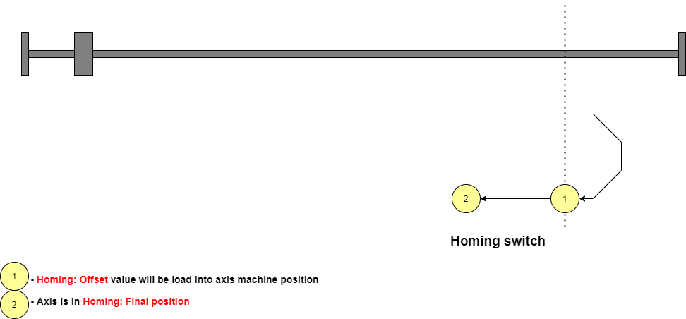
- If the Board Setting parameter
Homing: Index Inputis set, the Homing search procedure uses also the Index Input to archive more precision.
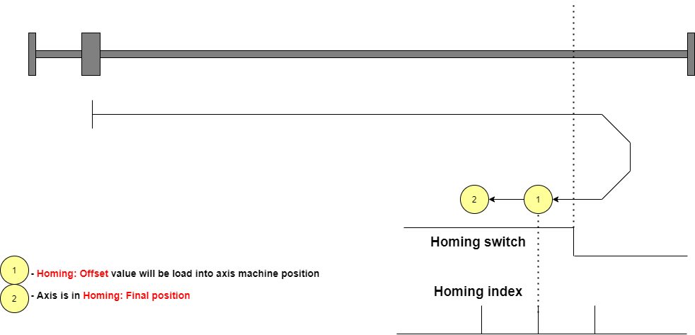


- Rising Edge
- This mode is very similar to Falling Edge but when the Homing sensor escapes, the axis will reverse direction again and load the machine position when the axis meets the homing sensor.
- This mode is used if the Homing sensor has a higher precision in the switching edge opposite to that defined in Falling Edge mode.
- Use this mode in combination with the Board Setting parameter
Homing: Index Inputis not permitted.
- This is an example with direction forward and Homing switch normally closed:
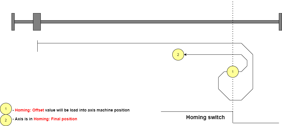

- Absolute
- This mode is used in the EtherCAT servo drive with an absolute encoder.
- No movement is commanded to the axis when the Homing Search procedure is started.
- The axis machine position will be loaded with the resulting value from the
Servodrive positionminus board setting parameterHoming: Offset.
- Absolute with final position
- Is the same as Absolute mode but after load the machine position the axis is moved to
Homing: Final Position.
- Pushing
- This mode is not yet implemented. It is reserved for intelligent servo drive that implements a homing procedure by its firmware.
- Pushing Switch Falling Edge
- This mode is very similar to Falling Edge.
- The axis moves to the selected direction (set by Board Setting parameter
Homing: Direction) until the axis meets the Homing sensor (Speed is set by Board Setting parameterHoming: Velocity), then a digital output is activated (selected by Board Setting parameterHoming: Pushing output) generally used to reduce the current in the stepper motor. The axes start a movement ofHoming: Pushing Positionvalue in the same direction to meet a mechanical lock. After that, the digital output will reset and the axis reverse direction to meet the homing sensor again as for Falling Edge mode. This mode is used when the axis step dir signals move two motors drive. The pushing movement is used to align the two axes thanks to the mechanical lock.
- This is an example with direction forward and Homing switch normally closed:
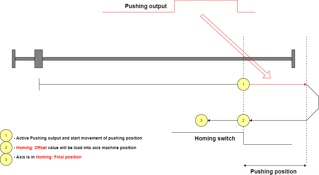

- Pushing Switch Rising Edge
- This mode is very similar to Pushing Switch Falling Edge but when the Homing sensor escapes, the axis will reverse direction again and load the machine position when the axis meets the homing sensor. This mode is used if the Homing sensor has a higher precision in the switching edge opposite to that defined in Pushing Switch Falling Edge mode. Use this mode in combination with the Board Setting parameter
Homing: Index Inputis not permitted.
10.3 Other Configurations
10.3.1 Homing Sequence
When a Home Search is started for All axes it is possible to define the order of axis execution.
Each axis has a Board setting parameter Homing: Sequence. Possible values are from 1 to 6.
Initially, the Home Search the Home Search is started for all axes set to Sequence 1, after axes with Sequence 2, and so on up to Sequence 6.
For a simple three-axis mill machine a typical set is Z-axis with sequence 1 and X and Y axes with sequence 2.
10.3.2 Axis acceleration
For every axis, it is possible to define the acceleration and the deceleration value during Home Search (see Homing: Acceleration and Homing Deceleration).
Please note that deceleration is important if the machine reference position is closed to a mechanical lock.
When the axis is searching the Homing Sensor at Homing: Velocity, it will travel an extra space due to deceleration.
During this space, the axis must not meet the limit switch or the mechanical block.
To help this check the Board settings panel in RosettaCNC software calculate the Homing: Deceleration Space according to deceleration and velocity.
Please check that axis have this space between the machine reference point and limit switch (or the mechanical block).
10.3.3 Homing sensor shared with axis limit
To save machine cost and electrical complexity it is possible to share the same sensor for the Home Search procedure and for the axis Limit Switch.
To enable this share check the appropriate settings in Board Setting Inputs as shown in the following image:

In this way when a Home Search procedure is active the Homing input acts as Homing Sensor, in other cases the Homing input is the limit switch.
Please take care that if you share the sensor it is necessary to set the Homing: Final Position different from Homing: Offset to avoid that at the end of the home search the sensor will not yet active and causes a LIMIT Alarm.
10.3.4 Axes Homing Done Output
It is possible to use a button with a lamp to add to the CNC console the possibility to start Home Search procedure and show the Homing Done status.
To do this:
- Connect the button to a CNC Board User Input and set the Board Settings parameter
Start Axes Homing Inputaccording to the user input number. - Connect the lamp to a CNC Board User Output and set the Board Settings parameter
Axes Homing Doneaccording to the user output number.

10.3.5 Homing Correction Space
When the Home Search procedure for an axis ends, the CNC Board calculates the correction that the procedure has made to the machine position.
This value is displayed in the panel Setup → Board Monitor… → Home Corrections Space
The calculated value can be useful in two cases:
- To evaluate the accuracy of the Home sensor.
- If the Home Search procedure is performed, the machine position is corrected the first time.
- If the Home Search procedure is still run you can evaluate the accuracy and repeatability of your sensor.
- If the sensor were perfect, the Space Correction value would be zero otherwise the calculated correction value is the accuracy of the sensor.
- To check if the stepper motors lose steps.
- First of all, perform a Home Search procedure, then execute a complex G code part program with rapid movements.
- At the end of the execution, perform a Home Search again.
- If the correction value is large it means that steps have been lost in the axis.
- In this case, check that the acceleration or speed is not higher than the motor's capabilities.
10.3.6 Conditions without Home Search Performed
If the Home Search procedure has not been performed, dangerous conditions could occur.
In this case, the machine axis positions are not synchronized and the software limits cannot be applied.
The Allowed Commands without Homing Done, in the menu Setup → Board Settings → General panel, defines the CNC Board behavior in case of Home Search not executed.
Possible parameter options are:
- All
- Every command can be executed.
- Jog at Reduced Speed
- Jog movements are permitted but only at a safe speed (100 mm/min or 100 deg/min).
- The execution of a G-Code program/macro/MDI will not be possible and followed by the below UI message.
- None
- Jog movements are not permitted.
- The user must necessarily start a Home Search procedure.
- The execution of a G-Code program/macro/MDI will not be possible and followed by the below UI message.
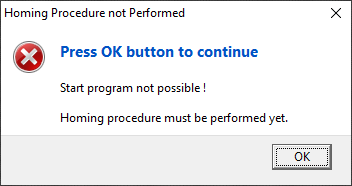

10.3.7 Invalidate Home Search status
If the CNC Board is controlling an axis with a Stepper Motor, when an ALARM occurs, the Axis Homing Search Done status will be reset.
The axis position, in the Control Software UI, will appear red-colored to indicate that the machine position could be not synchronized.
10.3.8 Disable the Single Axis Home Search
In some CNC configurations, it is never necessary to start a Home Search procedure on a single axis.
In these cases, the Homing button on the status bar can be configured to have the Home All axes function only.
To do this set the field Homing Button Type to Homing of all Axes in the menu Setup → Program Settings.. → ToolBar → Geneal sheet.
10.4 Gantry-Axes
A Gantry axis is a pair of axes that, due to the way the machine is built, must move at the same time and in synchronism.
At the CNC, only the movements of one of the axes must be programmed (the master or main gantry axis).
The other axis (slave gantry axis) is not programmable.
The CNC can manage a maximum of two gantry units. In the following description, reference is made only to gantry 1.
Now we discuss and show the homing search solutions in case of Gantry axis configuration.
Please note that in a gantry configuration during the Home Search it is also necessary to perform a movement to realign the axis, so that the two motors have a position that makes the axis movement without geometric errors.
There are three gantry axis configurations:
- Two drives connected to the same step-dir output.
- This is a very simple solution where two stepper drives are commanded by the same electrical signals. A simple solution to Home search this configuration is to connect a signal to reduce the motor current and a mechanical block near the machine reference point. Please see the description of
Pushing Switch Rising Edgemode for details.- Advantage: very simple solutions
- Disvantage: alignment accuracy depends on the cleanliness of the mechanical block
- Two drives connected to the same step dir output but with an external commutator that can temporarily disconnect one drive.
- In this solution, the step dir output normally commands two motor drives. But during Home Search, there is a moment in which digital output is activated and so only one motor moves while the other keep still. There are also two home switch sensors and the digital output when activated, connects the second sensor to the CNC.
- This way it is not necessary to have a mechanical block. The two motors align using their own homing sensors.
- Advantage: best precision, don't use two step-dir output.
- Disvantage: Need external commutator.
- Two drives connected to two step-dir outputs.
- In this solution, one CNC axis acts as gantry slave. So master maxis and slave axis have their own step dir output. Also every axis have its Home sensor. No extra electrical device are needed for this configuration.
- Advantage: don't need external commutator.
- Disvantage: Use CNC axis for slave gantry.
10.4.1 Gantry Configurations
10.4.1.1 Two drives connected to the same step-dir output.
This is a very simple configuration.
If stepper drivers support the motor current reduction by digital input, connect a RosettaCNC digital output as described in Pushing Switch Rising Edge mode.
Please note that steps for one motor revolution must be the same for the two motors.
Finally, make sure that the fault signals of the two drives are connected to the CNC.
10.4.1.2 Two drives connected to the same step dir output but with an external commutator that can temporarily disconnect one drive.
We call one axis master gantry and another slave gantry.
When the Home search procedure is started, both motors move and the axis uses the home sensor of the master gantry.
Then the external switches are activated and only the “slave gantry” motor moves and performs its home search using its home sensor.
To do this we need two external commutators connected to one RosettaCNC User Output. A commutator when activated interrupts the signals to the master gantry stepper drive.
The second switch is a diverter and when activated the signal of the slave gantry home switch is connected to the CNC (when it is deactivated the home sensor of the master gantry is connected to the CNC).
For the configuration:
- Homing parameters
- Set the axes Homing parameters (for example
Ysheet from the menuSetup → Board Settings… → Axes) as usual.
- Gantries parameters
- Set in
Gantry 1sheet from the menuSetup → Board Settings… → GantriesModetoUse only master motor controlMaster Axisto the master gantry (for exampleY)Homing: ModetoMaster held during alignmentHoming: Digital Outputto the User Output connected with commutatorsHoming: Max Disalignmentto the maximum space that the gantry axis can be misaligned.Homing: Switch Compensationto zero value initially. Then if the geometry of the gantry has errors it is possible to make a small correction by modifying this value instead of moving the position of the homing sensor.Max Disalignmentnot used in case ofUse only master motor controlmode.
Please note that:
- Steps for one motor revolution must be the same for the two motors.
- The fault signals of the two drives are connected to the CNC.
- The homing sensor must have the same logic (NC or NO).
- Same drives (for example the Delta ADS-B2 servo drive) has a digital input that suspends or interrupt the step dir information. In this case, it is possible to simplify the schematics and use only the diverter commutator.

10.4.1.3 Two drives connected to two step-dir outputs.
We call one axis master gantry and another slave gantry.
No the external commutator is needed. Every axis has its home sensor.
For the configuration:
- Homing parameters
- Set the master gantry Homing parameters (for example
Ysheet from the menuSetup → Board Settings… → Axes) as usual. - Set the slave gantry Homing parameters (for example
Asheet from the menuSetup → Board Settings… → Axes) as usual.
- Axis Type parameters
- Set the slave gantry axis ( for example
A) asSlave Axis of Gantry 1inMachinesheet from the menuSetup → Board Settings… → General).
- Gantries parameters
- Set in
Gantry 1sheet from the menuSetup → Board Settings… → GantriesModetoUse slave motor controlMaster Axisto the master gantry (for exampleY)Homing: ModetoMaster held during alignmentHoming: Digital Outputnor used in this case but it can be configured.Homing: Max Disalignmentto the maximum space that the gantry axis can be misaligned.Homing: Switch Compensationto zero value initially. Then if the geometry of the gantry has errors it is possible to make a small correction by modifying this value instead of moving the position of the homing sensor.Max Disalignmentused only in case of EtherCAT control.

11. Tool Change
A Tool Change procedure will be started every time that the M06 command is found and executed by CNC Board.
The Tool Change procedure will execute the external macro ( <machine>\macros\tool_change.ngc ) to do all required actions.
After the Control Software installation, a default tool_change.ngc macro is already available to supports most commons scenarios.
Is however possible to use a Text editor, or the Board Settings… → Tool Change → Macro editor, to modify the tool_change.ngc macro, and fit it to any CNC particular needs.
11.1 Tool Change Panel
The activity carried out by the CNC Board when executing a M06 command depends on the settings in the Setup → Board Settings… → Tool Change panel:
In the panel there are 4 fields:
- Tool Change Type
- Defines the way in which the CNC Board manages the
M06command between:
- None
- When a
M06command is found by the CNC Board none tool change procedure will be executed and the command will be ignored. - The loaded tool info will be set to
T0, the tool geometry and graphic toolpath color will use the default values. - In this case the H corrector (
G43/G43.1/G43.2/G43.4/G43.7) is correctly managed but requiresH<tool_number>argument to work, otherwise for default will beH0.
- Macro
- When a
M06command is found by the CNC board thetool_change.ngcmacro will be executed. - All actions to get the desired tool change procedure should be placed in that macro.
- The loaded tool info, the tool geometry, and the graphic toolpath color will be set to the tool specified with the
T<tool_number>command. - In this case the H corrector (
G43/G43.1/G43.2/G43.4/G43.7) is correctly managed andH<tool_number>argument is optional.
- PLC
- It is reserved for custom versions of the CNC Board in which the Tool Change management is carried out directly in the CNC instead of the external macro
tool_change.ngc. - Do not use without agreement and support from the CNC Board Support Team.
- Enable Slot ID
- This field is enabled only when the
Tool Change Typeset toMacro/PLC. - The Slot ID feature must be used ONLY if the CNC has an ATC (Automatic Tool Change) System.
- When the field is active it enables the possibility to define the Slot ID in the
Tools Library. - There are two IDs for each tool: Tool ID and Slot ID.
- The Tool ID corresponds to the tool number, therefore Tool ID 1 =
T1, Tool ID 99 =T99. - The Slot ID instead identifies the position of the tool in the tool magazine.
- Tool ID 5 with Slot ID 8 means that tool 5 is in position 8 of the tool magazine, for example, a rack.
- It will then be the task of the macro, suitably written for your machine configuration, to manage the unloading of the tool in use and the withdrawal of the new one from the slot specified during the macro call.
- Macro
- The Macro sheet contains the code of the tool change macro.
- The G-Code editor integrated into the panel allows you to examine and edit the macro contents.
- However, it is possible to examine and modify this macro also through a normal ASCII Text Editor such as NotePad++ by directly accessing the file in the folder:
%APPDATA%\RosettaCNC-1\machines\<your_machine_name>\macros\tool_change.ngc.- To fastly get into the macros folder you can also use the menu
File → Open Macros Folder.
- Enable Random Tool Changer
- The option is currently disabled but foreseen in the CNC Board to manage the case of tool changes where the Slot ID is random and corresponds to the first free and available one.
11.2 Libreria utensili
Per poter usare un utensile nel programma questo deve essere presente nella libreria utensili:

Tramite la libreria utensili è possibile assegnare le caratteristiche ad ogni utensile come: Tipo di utensile, diametro, lunghezza, offsets, etc. Ogni tipo di utensile ha impostazioni specifiche. Il parametro lunghezza, oltre che per la mera rappresentazione grafica, è indispensabile in caso di compensazione altezza utensile con le istruzioni:
- G43 Enable Tool Length Compensation
- G43.1 Enable Dynamic Tool Length Compensation
- G43.2 Apply additional Tool Length Offset
- G43.4 Enable RTCP Feature
- G43.7 Enable RTCP Feature and override tool offsets using user defined arguments
Nella libreria possono essere messi tutti gli utensili a disposizione mentre i campi Tool ID (ID utensile) e Slot ID possono essere variati a piacere per rappresentare la configurazione della lavorazione e quindi assegnare
l'ID utensile usato nel programma a un utensile nella libreria. Con il tasto destro del mouse compare un menu che permette di disabilitare tutti i Tool ID o Slot ID in un colpo solo e facilitare l'operazione della
riassegnazione degli ID.
La libreria utensili permette operazioni di Importazione / Esportazione per facilitare il salvataggio e recupero di una configurazione legata ad una lavorazione che potrebbe essere rieseguita molte volte nel tempo.
11.3 Macro cambio utensile
Al momento dell'installazione, nella cartella macros della macchina di default RosettaCNC
%HOMEPATH%/Documents/RosettaCNC-1/machine/RosettaCNC/macros/
è già presente il file tool_change.ngc con un esempio di macro per il cambio utensile di tipo manuale.
Questa macro è stata creata per supportare l'utente della CNC nelle configurazioni di cambio utensile manuale più comuni ma può essere modificata ed ampliata dall'utente stesso per meglio adattarsi alle proprie esigenze.
Inoltre per aumentare la flessibilità la macro può essere configurata nel comportamento tramite l'utilizzo dei parametri “Protected Variables” presenti nella “Libreria parametri” pannello “Protected”:

Il parametro 6000 definisce il comportamento del cambio utensile. Al momento è definito solo il comportamento per il valore zero. Nel capitolo successivo è illustrata questa implementazione.
11.4 Tool Change Type 0 - Misura automatica lunghezza utensile
Con questo tipo di cambio utensile si ottiene la misurazione automatica della lunghezza utensile in uso.
Esso si applica sia nel caso di mandrini porta utensili a pinza fissa che con mandrini con cono in qui non si voglia gestire la fase di PRE-SETTINGS.
Dato che, durante la procedura di cambio, la “Lunghezza” utensile viene automaticamente misurata il relativo campo nella tabella utensili ha solo funzione grafica.
Un esempio di mandrino a pinza fissa è illustrato nella seguente figura:

Per la misurazione della lunghezza utensile è necessario avere un sensore di acquisizione (TOOL LENGTH PROBE) a posizione meccanica nota.
Un esempio di sensore è illustrato nella seguente figura:

Il compilatore del codice G richiede che in libreria utensili vi siano tutti gli utensili usati da un programma.
L'uso di questa macro, in ogni caso, permette di poter trascurare il campo Lunghezza in quanto tale valore verrà calcolato in automatico dalla macro stessa.
Vediamo in dettaglio la sequenza di utilizzo di questo cambio utensile.
Si suppone per semplicità che il G-Code da eseguire sia generato con zero sulla sommità pezzo.
- Si predispone sul mandrino il primo utensile usato dalla lavorazione.
- Si esegue lo zero pezzo sul materiale.
- Viene avviata la lavorazione.
- Appena la CNC incontrata l'istruzione
Tn M6la macro va a misurare la lunghezza dell'utensile corrente.
- Fatta la misurazione la CNC si porta nella posizione di cambio utensile e attende che venga effettuato il cambio dall'operatore.
A questo punto comparirà il seguente pannello con la descrizione dell'utensile da caricare:
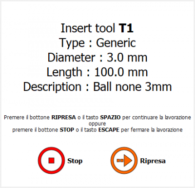
Nel caso in cui l'utensile caricato sia già quello richiesto è sufficiente confermare l'operazione con Ripresa.
- Viene quindi effettuata una nuova misurazione della lunghezza dell'utensile appena caricato.
- Viene calcolato un valore di differenza e messo in esecuzione come
G43.1“Enable Dynamic Tool Length Compensation”.
Tale valore sarà visibile nel campo informazioni utensile in uso della Status Bar:
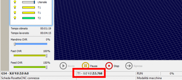
- L'esecuzione prosegue con la lavorazione per l'utensile attivo.
- Appena viene incontrata un'altra istruzione
Tn M6la procedura va a rimisurare la lunghezza dell'utensile corrente e ripete le operazioni del punto 5 fino a fine programma.


11.4.1 Note
Alcune note importanti:
- Per un corretto funzionamento l'impostazione “G43 persistente” deve essere disattiva.
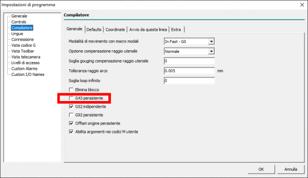
- Questa procedura utilizza la lunghezza utensili per rappresentare una differenza tra l'utensile scaricato e quello caricato durante la procedura di cambio utensile.
Tale valore viene messo in esecuzione come valore immediato “G43.1 Zn” e non viene salvato nella libreria utensili. - Il part program NON deve contenere istruzioni di compensazione lunghezza utensile ”
G43/G43.1/G43.2/G45/G47“ o di annullamento della stessa ”G49“. - La misurazione avviene sempre con due tocchi. Il secondo è effettuato ad una velocità ridotta per aumentare la precisione e ripetibilità.

11.4.2 Parametri
Vediamo in dettaglio i parametri da impostare per caratterizzare il funzionamento:
| Parameter | Name | Description |
|---|---|---|
| #6000 | TOOL_CHANGE : Tool change type: | Impostare a zero. |
| #6001 | TOOL_CHANGE : Tool change features: | 0 = non ritorna al punto XY iniziale. 1 = ritorna al punto XY iniziale |
| #6002 | TOOL_CHANGE : Tool change position X (MCS) | posizione X macchina dove l'operatore effettua il cambio utensile |
| #6003 | TOOL_CHANGE : Tool change position Y (MCS) | posizione Y macchina dove l'operatore effettua il cambio utensile |
| #6004 | TOOL_CHANGE : Tool change position Z (MCS) | posizione Z macchina dove l'operatore effettua il cambio utensile |
| #6005 | TOOL_CHANGE : Sensor safe position Z (MCS) | posizione di sicurezza Z usate per attraversare il piano di lavoro e raggiungere le coordinate sensore o cambio utensile |
| #6006 | TOOL_CHANGE : Sensor top/center position X (MCS) | posizione X macchina dove si trova il sensore di misura |
| #6007 | TOOL_CHANGE : Sensor top/center position Y (MCS) | posizione Y macchina dove si trova il sensore di misura |
| #6008 | TOOL_CHANGE : Sensor top/center position Z (MCS) | posizione Z alla quale il mandrino toccherebbe il sensore se fosse privo di utensile |
| #6009 | TOOL_CHANGE : Feed during tool change procedure | feed durante i movimenti di attraversamento |
| #6010 | TOOL_CHANGE : Z approaching sensor position (MCS, reached with FAST feed #6011) | posizione Z alla quale il mandrino scende ad una velocità elevata. Questa quota va impostata in modo che anche con l'utensile più lungo utilizzabile non venga mai premuto il sensore. |
| #6011 | TOOL_CHANGE : Z feed to sensor approaching (FAST) | feed durante la discesa rapida verso il sensore |
| #6012 | TOOL_CHANGE : Z feed to 1st probe input capture (SLOW) | feed durante la prima discesa. Impostare una velocità bassa. |
| #6013 | TOOL_CHANGE : Z feed to 2nd probe input capture (VERY SLOW) | feed durante la seconda discesa. Impostare una velocità molto bassa per aumentare la precisione. |
| #6014 | TOOL_CHANGE : Z up movement after 1st touch capture (REL) | spazio eseguito dall'asse Z per disimpegnare il sensore e prepararsi al secondo tocco. Inserire un valore piccolo, per esempio 3.0 mm |
| #6015 | TOOL_CHANGE : Minimum tool lenght accepted | corrisponde alla lunghezza dell'utensile più corto che si vuole usare. E' un valore utilizzato durante il movimento per il secondo tocco, l'asse Z scende fino ad un valore indicato dal parametro 6008 maggiorato del presente parametro. |
12. Plasma Torch
Starting from version 1.7 the management of the Plasma Torch has been added.
For plasma management it is possible to add an external THC (Torch Height Control) device to obtain control of the torch height.
An example of a widely used THC device could be the THC 150 model of the Proma Elektronika company.

The THC 150 provides three output digital signals to the CNC:
- UP: The torch must be raised.
- DOWN: The torch must be lowered.
- ARC: The arc under the torch is active.
All these digital signals are connected to the RosettaCNC user inputs.
The number of the user input to be used is not restricted, in the RosettaCNC settings it will be necessary to set the number of the user input chosen for each signal.
12.1 Plasma Torch and Spindle
The management of the Plasma Torch is decoupled from the management of Spindle, therefore it is possible to have mounted in same head of CNC a normal Spindle and a Plasma Torch.
Spindle and Plasma Torch have separate digital output signals but share same activation/deactivation G-code (M3 and M5).
When the loaded tool is of type Plasma M3 become Torch ON command and M5 will be Torch OFF command. M4 will have same behavior of M5.
Also the Spindle CW Input, Spindle CCW Input and Spindle Stop Input will be disabled.
- Example of Plasma Torch Tool definition in Tools Library:
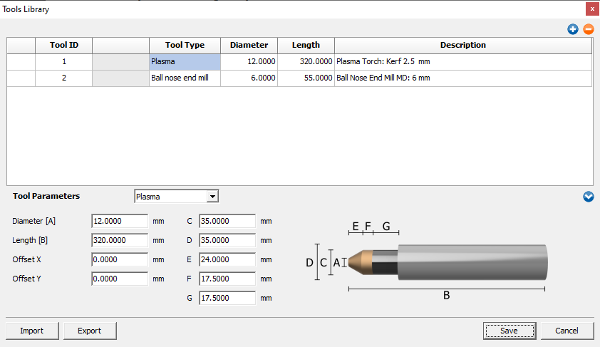

When the loaded tool is of any other type M3 become Spindle CW and command M5 will be Spindle Stop. M4 will be Spindle CCW.
The Spindle CW Input, Spindle CCW Input and Spindle Stop Input if configurated will be enabled.
- Example of Ball Nose End Mill tool definition in Tools Library:
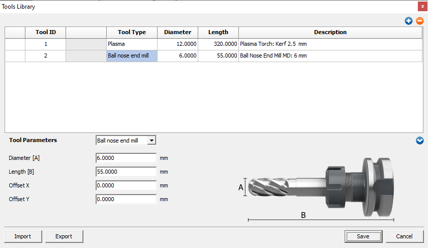

To work with Plasma Torch is necessary to correctly define and load a Plasma tool.
This requires that the Tool Change Type parameter, in the Tool Change panel on RosettaCNC Board Settings, is set to Macro and that the tool change macro is correctly configurated for your machine.
12.2 Configuration
The configuration of Plasma Torch and Torch Height Control is defined in the Plasma Torch panel in the RosettaCNC tab settings.

Let's see in detail the meaning of each parameter:
- Enable Plasma Torch : Used to enable THC control. If the control is disabled and an instruction
M17orM18is present in the G-code, the alarm would appear:

- Torch Velocity : Indicates the Z axis velocity when it is controlled by the THC. It is a percentage value of Z axis maximum speed.
- Torch Disable Velocity : Indicates a percentage of the feed set which the THC control is automatically disabled. Setting zero to disable the function. For more details see the dedicated chapter.
- Torch Acceleration Override : Indicates the acceleration of the Z axis during the THC check. 100% means as axis setting, 50% means half acceleration.
- Torch Up Input : It is the number of the user input and the type of logic dedicated to this function.
- Torch Dwon Input : It is the number of the user input and the type of logic dedicated to this function.
- Torch Arc OK Input : It is the number of the user input and the type of logic dedicated to this function. Its programming is optional. For more details see the dedicated chapter.
- Torch Anti-Collision Input : It is the number of the user input and the type of logic dedicated to this function. Its programming is optional. If the THC control is active (
M17) RosettaCNC continuously monitors the signal and if it indicates a collision, the machining is immediately stopped and the alarm would appear:

- M3 (Plasma Torch ON) : It is the number of user output that sets the plasma torch state.
- M17 (Torch Control Height ON) : It is also possible to configure a digital output that is activated when the Z axis is controlled by the THC device.


12.3 Operation
The CNC enters in Plasma Mode when a tool of PLASMA type il loaded with Tn M6 or M61 Qn G-code instructions.
The CNC exits from Plasma Mode when any other type of tool is loaded with Tn M6 or M61 Qn G-code instructions.
During PLASMA tool loading the CNC checks if Enable Plasma Torch setup parameter is OFF, in this case the CNC will enters in ALARM state:

When CNC is in Plasma Mode:
M3actives the Plasma Torch output.
M4/M5deactives the Plasma Torch output.
M17enables the THC device control of Z axis height.
M18disables the THC device control of Z axis height.
The M17 instruction activates the Z axis control by THC. When this instruction is encountered, RosettaCNC saves the current Z axis position, then disconnects the axis from the interpolation and commands it via the Up torch and Down torch inputs. When the instruction M18 is met RosettaCNC maintains the current position up to a new command Z instruction inside the G-code. During the THC check, a digital output, if configured, is activated to manage any external electromechanical logic.
The G-code instruction M17 can place CNC in ALARM state:

This happens in the following cases:
- The Z axis is not enabled in the settings.
- The “Enable plasma Torch” parameter is not active.
- Up Torch or Down Torch inputs have not been configured.
12.3.1 "Torch Arc Ok" Input
The Torch Arc OK input signal can be set to any generic user input or leaved NOT configured in the “Plasma torch” panel.
When assigned to an user input it is possible to wait and verify that the arc is activated by, for example, instruction M66 P1 L1 after power on the torch with M3.
However, if you wish also that RosettaCNC continuously verifies the presence of the “Torch Arc Ok” input signal when the THC is active, then it must be configured.
In this way you can continue to use the check with instruction M66 P1 L1 and if the arc became not active, an alarm during THC enable is generated
 .
.
In other words, while the THC is active, if the “Torch Arch Ok” signal becomes or is already active, it can no longer be deactivated until the THC is disabled.

12.3.2 Z position after M18
When the THC is active, the Z position assumes a value different from that expressed by the G-code.
The M18 command (that deactivates the THC) must also return the Z position to the value expressed by the G-code.
This movement takes place in the following way: at the first movement instruction following the code M18 (even if it does not explicitly include the letter Z) the CN performs a check if an upward movement is necessary to reach the target position.
In the negative case (negative movement need) the CNC enters in ALARM state:

Otherwise the new movement includes a movement of Z from the current position to the new target position expressed in the G-code.
So in general it is necessary to verify in the post processor that the first move instruction after M18 includes a climb movement Z to a safety altitude.
12.3.3 Torch Disable Velocity
The Torch Disable Velocity parameter, when greater than 0%, enables continuous monitoring of the interpolation feed rate.
During movements with THC Control Enabled (M17) if interpolation feed rate decreases by percentage respect to the set value, the CNC automatically suspends the THC Control.
This is useful if the feed speed is decreased by the interpolator to respect the axis accelerations, for eg.during an axis direction change.
Let's take an example:
- Set the Torch Disable Velocity parameter to 80%.
- The plasma cutting to be performed has been described in the G-Code program with
F1000. - Suppose we work with Feed Override at 100%.
- If, for example, during an axis change direction the feed rate decreases below 800mm/min the THC UP/DOWN signals are temporary ignored till the speed returns at least to 800mm/min.
Another example:
- Set the Torch Disable Velocity parameter to 80%.
- The plasma cutting to be performed has been described in the G-Code program with
F3000. - During the cut the operator sees that the best result is obtained with a 70% Override (therefore 2100mm/min).
- If the feed rate decreases below 1680mm/min (80% of 2100) the THC UP/DOWN signals will be temporary ignored till the speed returns at least to 1680mm/min.
12.4 Torch Toolbar Icon
It is possible to have in the toolbar the icon of Plasma Torch output state enabling related icon Visible checkbox on Toolbar View panel of Program Settings.
It is also possible to enable the icon to change Plasma Torch output state enabling realeted icon Enabled checkbox.
The change of Plasma Torch output state between icon toolbar will be possibile ONLY when CNC is in IDLE state.
![]()
Resulting toolbar view:
![]()
12.5 THC Disable Toolbar Icon
It is possible to have in the toolbar the icon of THC Disable control enabling related icon Visible checkbox on Toolbar View panel of Program Settings.
It is also possibile to enable the icon to change the THC Disable state enabling related icon Enabled checkbox.
The change of THC disable state is possible both before the execution of a G-code and during the execution of a G-code.
If the THC is disabled the Z axis keep the position.
![]()
Resulting toolbar view:
![]()
The set disable state is not kept after a CNC shutdown.
12.6 UI View
When a Plasma Torch tool is active an extra panel is shown at top/right place in toolpath scene.
The panel indicates that CNC is in Plasma mode and two LEDs show the Plasma Torch and THC control state.

An overall view of Plasma Torch CNC is the following:

12.7 Important Notes
- At the end of the G-code the THC control is automatically disabled.
- When the THC is enabled (
M17) any programmed Z movement in the G-code will be ignored. - During the THC control the Z movements can extend between the minimum machine position and the maximum machine position value.
- If the “Torch Up Input” and “Torch Down Input” are active simultaneously (abnormal condition) no movement is performed and no alarm is generated.
13. ATC Management
When the CNC has an ATC System the Control Software can help the phase of Tools Setup through a dedicated user panel, the ATC Management.
The ATC Management panel is available and enabled in “Functions –> ATC Management” menu only if following requirements are satified:

- The CNC has the tool change macro (tool_change.ngc) and “Tool Change Type” parameter is set to Macro.
- The “Enable Slot Id” parameter is checked.
- If you are using the default tool change macro from Control Software installation the macro should be well configurated
through related “Parameters Library” dialog in Protected sheet (see related documentations for parameters values):
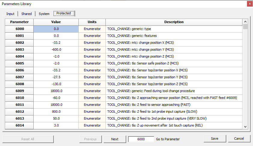

In the Tool Setup Commands panel there are six action buttons:
- Clear Selected Slot
- Clear All Slots
- Manual Release
- Open/Close Cart
- Pick & Place Tool
- Preset Tools
13.1 Set Loaded Tool Macro
Default skeleton Macro sample:
;
;   RosettaCNC (c) 2016-2020
;
;   Name            : atcm_set_loaded_tool
;   Sub UID         : 1
;   Version         : 1
;   Description     : set loaded tool action
;   Note            : use M99 as macro exit call
;                   : TAKE CARE: following is only a skeleton macro sample
;
;   Inputs:
;
;       Parameter                           Description
;       =========                           ===========
;       #<atcm.tool_id>                     tool id to set as loaded in the spindle
;
O1
    ; !!! REMOVE BELOW SKELETON MACRO SAMPLE & PLACE YOUR ACTION CODE HERE !!!

    ; notices PLC about spindle loaded tool id
    M61 Q#<atcm.tool_id>

    ; shows HUD (Heads-Up Display) message for a while
    M109 P"ATCM - Set Loaded Tool in the Spindle: #<atcm.tool_id>..." Q4
    G4 P2

M99
13.2 Manual Release Macro
Default skeleton Macro sample:
;
;   RosettaCNC (c) 2016-2020
;
;   Name            : atcm_manual_release
;   Sub UID         : 1
;   Version         : 1
;   Description     : manual release action
;   Note            : use M99 as macro exit call
;                   : TAKE CARE: following is only a skeleton macro sample
;
O1
    ; !!! REMOVE BELOW SKELETON MACRO SAMPLE & PLACE YOUR ACTION CODE HERE !!!

    ; notices PLC about spindle with none tool loaded because was released
    M61 Q0

    ; shows HUD (Heads-Up Display) message for a while
    M109 P"ATCM - Manual Release..." Q4
    G4 P2

M99
13.3 Open/Close Cart Macro
Default skeleton Macro sample:
;
;   RosettaCNC (c) 2016-2020
;
;   Name            : atcm_open_close_cart
;   Sub UID         : 1
;   Version         : 1
;   Description     : open/close action
;   Note            : use M99 as macro exit call
;                   : TAKE CARE: following is only a skeleton macro sample
;
O1
    ; !!! REMOVE BELOW SKELETON MACRO SAMPLE & PLACE YOUR ACTION CODE HERE !!!

    ; shows HUD (Heads-Up Display) message for a while
    M109 P"ATCM - Open/Close Cart..." Q4
    G4 P2

M99
13.4 Pick & Place Tool Macro
The Pick/Place action can be used to:
- Pick: pick a tool from the selected slot.
- Place: place the loaded tool in the related slot.
- Place & Pick: place the loaded tool in the related slot and Pick the loaded tool from the selected slot.
The action button is enabled if:
- Connection with CNC is active.
- CNC is in IDLE state.
- One slot is checked and none tool is loaded (Pick action).
- One slot is checked and is the same assigned to loaded tool (Place action).
- None slot is checked and the loaded tool has an assigned slot (Place action).
The Pick/Place action can be executed clicking Pick/Place button or pressing F9 key.
The Pick/Place action call the external macro atc_pick_place.ngc which implements required G-code program.
The inputs of macro are:
  #<atc.pick_place.mode>            ; contains the pick/place mode: 0 = pick, 1 = place

  ; in case of a place mode
  ;
  #<atc.pick_place.tool_id>=3       ; contains pick/place tool ID to pick
  #<atc.pick.place_slot_id>=1       ; contains pick/place slot ID to pick

  ; in case of a pick mode
  #<atc.pick_place.tool_id>=3       ; contains pick/place tool ID to place
  #<atc.pick.palce.slot_id>=1       ; contains pick/place slot ID to place
Default skeleton Macro sample:
;
;   RosettaCNC (c) 2016-2020
;
;   Name            : atcm_pick_place_tool
;   Sub UID         : 1
;   Version         : 1
;   Description     : pick/place tool action
;   Note            : use M99 as macro exit call
;                   : TAKE CARE: following is only a skeleton macro sample
;
;   Inputs:
;
;       Parameter                               Description
;       =========                               ===========
;       #<atcm.pick_place.mode>                 pick & place mode:
;                                                   #<pick_place.mode_pick>       = pick tool action
;                                                   #<pick_place.mode_place>      = place tool action
;                                                   #<pick_place.mode_place_pick> = place/pick tool action
;       #<atcm.pick.slot_id>                    slot id to pick
;       #<atcm.pick.slot_id>                    tool id to pick
;       #<atcm.place.tool_id>                   slot id to place
;       #<atcm.place.slot_id>                   tool id to place
;
O1
    ; !!! REMOVE BELOW SKELETON MACRO SAMPLE & PLACE YOUR ACTION CODE HERE !!!

    ; checks if request a pick action
    IF [#<atcm.pick_place.mode> EQ #<pick_place.mode_pick>] THEN01

        ; shows pick action parameters
        M109 P"<B>ATCM - Pick/Place</B><BR><BR>Mode = Pick Tool<BR>Slot ID = #<atcm.pick.slot_id><BR>Tool ID = #<atcm.pick.slot_id>" Q2
        M99

    END01

    ; checks if request a place action
    IF [#<atcm.pick_place.mode> EQ #<pick_place.mode_place>] THEN01

        ; shows place action parameters
        M109 P"<B>ATCM - Pick/Place</B><BR><BR>Mode = Place Tool<BR>Slot ID = #<atcm.place.tool_id><BR>Tool ID = #<atcm.place.slot_id>" Q2
        M99

    END01

    ; checks if request a pick/place action
    IF [#<atcm.pick_place.mode> EQ #<pick_place.mode_place_pick>] THEN01

        ; shows pick/place action parameters
        M109 P"<B>ATCM - Pick/Place</B><BR><BR>Mode = Pick/Place Tool<BR>Place: Slot ID = #<atcm.place.tool_id>, Tool ID = #<atcm.place.slot_id><BR>Pick: Slot ID = #<atcm.pick.slot_id>, Tool ID = #<atcm.pick.slot_id>" Q2
        M99

    END01

    ; notices wrong pick/place mode
    M109 P"<B>ATC Pick/Place</B><BR><BR>Mode = #<atcm.pick_place.mode><BR><BR><B>Unsupported Mode</B>" Q2

M99
13.5 Preset Tools Macro
Default skeleton Macro sample:
;
;   RosettaCNC (c) 2016-2020
;
;   Name            : atcm_preset_tools
;   Sub UID         : 1
;   Version         : 1
;   Description     : preset tools action
;   Note            : use M99 as macro exit call
;                   : TAKE CARE: following is only a skeleton macro sample
;
;   Inputs:
;
;       Parameter                               Description
;       =========                               ===========
;       #<atcm.preset_tools.count>              number of selected tools to preset
;       #<atcm.preset_tools.slot_id[n]>         array with slot id of selected tool to preset ([n] = 1..#<atcm.preset_tools.count>)
;       #<atcm.preset_tools.tool_id[n]>         array with tool id of selected tool to preset ([n] = 1..#<atcm.preset_tools.count>)
;       #<atcm.preset_tools.loaded.slot_id>     slot id of loaded tool to preset (0 = no loaded tool in the spindle)
;       #<atcm.preset_tools.loaded.tool_id>     tool id of loaded tool to preset (0 = no loaded tool in the spindle)
;
O1
    ; !!! REMOVE BELOW SKELETON MACRO SAMPLE & PLACE YOUR ACTION CODE HERE !!!

    M109 P"ATCM - Preset of Tools" Q4

    ; checks if there is a loaded tool in the spindle
    IF [#<atcm.preset_tools.loaded.tool_id> NE 0] THEN01

        #<_slot_> = #<atcm.preset_tools.loaded.slot_id>
        #<_tool_> = #<atcm.preset_tools.loaded.tool_id>

        ; shows loaded tool to preset info
        M109 P"<B>ATCM - Preset Loaded Tool</B><BR><BR>Slot ID = #<_slot_><BR>ToolID = #<_tool_>" Q2

        ; place here code for preset loaded tool
        ; Xxx

    END01

    ; parses tools to do a preset and shows related infos
    #<_i_> = 1
    WHILE [#<_i_> LE #<atcm.preset_tools.count>] DO01

        #<_slot_> = #<atcm.preset_tools.slot_id[#<_i_>]>
        #<_tool_> = #<atcm.preset_tools.tool_id[#<_i_>]>

        ; checks if selected tool is not the loaded tool already presetted
        IF [#<_tool_> NE #<atcm.preset_tools.loaded.tool_id>] THEN02

            ; shows tool to preset info
            M109 P"<B>ATCM - Preset Selected Tool</B><BR><BR>Slot ID = #<_slot_><BR>ToolID = #<_tool_>" Q2

            ; place here code for preset tool
            ; Xxx

        END02

        #<_i_> = [#<_i_> + 1]
    END01

M99


16. Internationalization
The Control Software integrates a Languange Engine which permits to switch UI language from a list of available languages.
The UI Language Engine uses gettext, a standard internationalization and localization system commonly used for writing multilingual programs.
To edit an existent language, or add a new language to the Control Software, you can use the program Poedit.
Poedit exists in the freeware version or in the PRO version, which adds a lot of useful features to reduce the translation time and increase translation accuracy.
There are other translation tools that manage gettext .po/.mo files but in this document, we will use Poedit.
16.1 UI Localization
In gettext for each language translations there are one or two files:
- default.mo
- This file contains the compiled language translations and is directly used by Control Software.
- PS: This file is mandatory in Control Software Language Engine.
- default.po
- This file contains the language translations project used by Poedit.
- As the final step, of a language translation, Poedit will compile the
default.pofile to get thedefault.mo. - PS: This file is used only by Poedit to generate the
default.mofile. 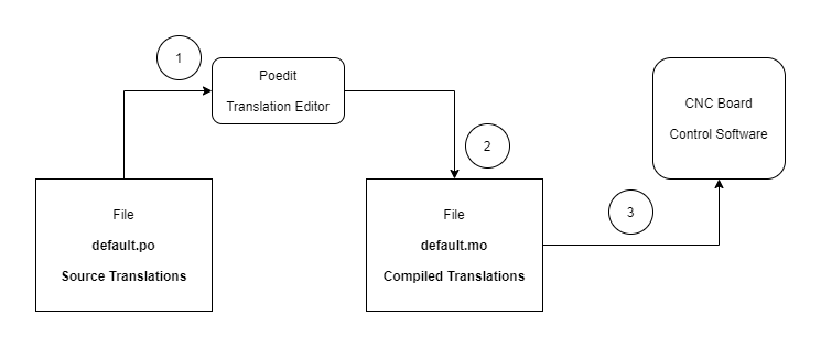
As shown in the upon scheme:
- The source translation file
default.pois loaded in Poedit translator for the translation in the target language. - When the translation is done or only desired texts are done the Poedit creates del output file
default.mo. - The Control Software, during starting, check for available translation languages and load
default.mowith translated texts.
16.2 Unicode
Both gettext and Poedit support Unicode texts, so default.po and default.mo will contain Unicode translations.
16.3 gettext Path Organization
The gettext Language Engine needs a well-defined path organization where to get info about available translation languages.
The Control Software reaches the translations files from %APPDATA\RosettaCNC-1\locale folder:
%APPDATA%\RosettaCNC-1\locale
                       |
                       + default.po (this is the main translation file to use to add a new language translation or merge already translated with new version).
                       |
		       +--\de
		       |   |
		       |   +----\LC_MESSAGES\default.mo  (Compiled Translation File for German)
		       |
		       +--\en
		       |   |
		       |   +----\LC_MESSAGES\default.mo  (Compiled Translation File for English)
		       |                    \default.po  (Source Translation File for Poedit)
		       |
		       +--\fr_FR
		       |   |
		       |   +----\LC_MESSAGES\default.mo  (Translation File for Francaise of France)
		       |
		       +--\it_IT
		       |   |
		       |   +----\LC_MESSAGES\default.mo  (Translation File for Italian of Italy)
		       |
		       +--\pt_BR
		           |
		           +----\LC_MESSAGES\default.mo  (Translation File for Portughese of Brazil)
The folders after locale define the translation language ad use the ISO 639-1 standard ( List of ISO 639-1 codes ).
The ISO 639-1 permits to define a language (e.g. en for common English) or a derivation of a language for a specific country (e.g: en_CA English for Canada).
The locale\en\LC_MESSAGES folder is then only that contains also the Source Translation File for Poedit ( poedit.po ) to use to create a new translation language.
The Control Software texts are natively in English so actually no need for any translation and poedit.mo will be an empty container.
16.4 Add a New Language
To add a new language, e.g. Spanish, the steps to do are:
- Close any open instance of the Control Software.
- Copy/Paste the
enfolder, available in%APPDATA%\RosettaCNC-1\localein%APPDATA%\RosettaCNC-1\locale.
- Rename the copied folder to
..\locale\esfolder to to have the%APPDATA%\RosettaCNC-1\locale\esand related sub-folders. - Run the Poedit and open
%APPDATA%\RosettaCNC-1\locale\sp\LC_MESSAGES\default.pofile or double click on it in Explorer to start Poedit and load it.
At this point Poedit will indicate to you that a Language of the Translation isn't set:

Clicking on the Set Language button will appear the Catalogue properties panel to define the Language, Charset, and info about translator identity:

Now the editor is ready to receive translations from English to Spanish.
16.4.1 Rules to Follow
- The Source Text will be always unmodifiable and in English, the native language of Control Software.
- Any untranslated text will remain in English in the Control Software UI.
- To be untranslated the Translation row must be empty without any space char or translation will be an empty string.
- Keep translation text shorter possible, or close to English string chars, not all UI fields have a width space for long strings.
- If Source Text has header/tail spaces these MUST be used also in the Translation.
- If Source Text uses HTML Tags SAME HTML Tags MUST be present also in the Translation.
- If Sorce Text presents data wildcard (
%sfor string,%dfor data,%ffor load or\n, etc. these MUST be present in same order also in the Translation.
The last point is very IMPORTANT because a missing or wrong order in a wildcard can produce an issue in the Translation Engine.
A practical way to translate a text is to copy the original one from the Source Text row to the Translate row and after modify the contents.
In this mode, it is more improbable to miss or mistake the order of wildcards or special chars.
16.5 Save and Create Translation
To save the translation project and create the final translation file default.mo is only necessary to click the Save button in the toolbar:

The resulting localization path will be:
%APPDATA%\RosettaCNC-1\locale
                       |
		       +--\de
		       |   |
		       |   +----\LC_MESSAGES\default.mo  (Compiled Translation File for German)
		       |
		       +--\en
		       |   |
		       |   +----\LC_MESSAGES\default.mo  (Compiled Translation File for English)
		       |                    \default.po  (Source Translation File for Poedit)
		       |
		       +--\fr_FR
		       |   |
		       |   +----\LC_MESSAGES\default.mo  (Translation File for Francaise of France)
		       |
		       +--\it_IT
		       |   |
		       |   +----\LC_MESSAGES\default.mo  (Translation File for Italian of Italy)
		       |
		       +--\pt_BR
		       |   |
		       |   +----\LC_MESSAGES\default.mo  (Translation File for Portughese of Brazil)
		       |
		       +--\es
		           |
		           +----\LC_MESSAGES\default.mo  (Translation File for Spanish)
		                            \default.po  (Source Translation File for Poedit with Spanish Texts)
16.6 Check the Translation
To check the translation just Start Control Software and choose the Spanish language in menu Program Settings… at Languages panel:

16.7 Translation Management
Every Control Software update or new version adds or changes some text so it is important to manage translations in time.
For a better management of a newly added language, we suggest saving the source translated file default.po for future translations.
Much better if you will send the file to support@rosettacnc.com, in this way we will add it to the new installation packages and we will maintain the new entry texts in that language.
17. Keyboard and Key Shortcuts
| Main Menu | Function | Control Keys | Key | Description |
|---|---|---|---|---|
| File | ||||
| Open File… | F12 | |||
| |
||||
| Save | Ctrl | S | ||
| Edit | ||||
| Undo | Ctrl | Z | ||
| Redo | Shift + Ctrl | Z | ||
| |
||||
| Find | Ctrl | F | ||
| Replace | Ctrl | R | ||
| Search Again | Ctrl | N | ||
| |
||||
| Go to Line Number… | Ctrl | G | ||
| View | ||||
| Show Grid | Alt | 1 | ||
| Show DRO Monitor | Alt | 2 | ||
| Show TCP Extents in Feed | Alt | 4 | ||
| Show Machine Toolbar | Alt | 5 | ||
| Show MCS Origin Guide | Alt | 6 | ||
| Show Active WCS Origin Guide | Alt | 7 | ||
| Show Rotary Guide for Axis A | Alt | 8 | ||
| Show Rotary Guide for Axis B | Alt | 9 | ||
| Show Rotary Guide for Axis C | Alt | 0 | ||
| |
||||
| Show Jog Controls | F1 | |||
| Show Machining Info | F2 | |||
| Show Dynamic Offsets | F3 | |||
| Show MDI Commands | F4 | |||
| Show Simulator Controls | F5 | |||
| |
||||
| Toogle Fullscreen | F11 | |||
| Machine | ||||
| Start | Ctrl | F5 | ||
| Stop | Ctrl | F7 | ||
| Resume | Ctrl | F8 | ||
| |
||||
| Go to Position | Ctrl | F9 | ||
| |
||||
| Define Tool In Spindle… | Ctrl | F10 | ||
| |
||||
| Reset Alarms | Ctrl | F11 | ||
| G-Code Editor | Function | Control Keys | Key | Description |
|---|---|---|---|---|
| Analyze G-Code | F9 | |||
| |
||||
| Up | UP | |||
| Sel Up | Shift | UP | ||
| Scroll Up | Ctrl | UP | ||
| Down | DOWN | |||
| Sel Down | Shift | DOWN | ||
| Scroll Down | Ctrl | DOWN | ||
| Left | LEFT | |||
| Sel Left | Shift | LEFT | ||
| Word Left | Ctrl | LEFT | ||
| Sel Word Left | Shift + Ctrl | LEFT | ||
| Right | RIGHT | |||
| Sel Right | Shift | RIGHT | ||
| Word Right | Ctrl | RIGHT | ||
| Sel Word Right | Shift + Ctrl | RIGHT | ||
| Page Down | NEXT | |||
| Sel Page Down | Shift | NEXT | ||
| Page Bottom | Ctrl | NEXT | ||
| Sel Page Bottom | Shift + Ctrl | NEXT | ||
| Page Up | PRIOR | |||
| Sel Page Up | Shift | PRIOR | ||
| Page Top | Ctrl | PRIOR | ||
| Sel Page Top | Shift + Ctrl | PRIOR | ||
| Line Start | HOME | |||
| Sel Line Start | Shift | HOME | ||
| Editor Top | Ctrl | HOME | ||
| Sel Editor Top | Shift + Ctrl | HOME | ||
| Line End | END | |||
| Sel Line End | Shift | END | ||
| Editor Bottom | Ctrl | END | ||
| Sel Editor Bottom | Shift + Ctrl | END | ||
| Toggle Mode | INSERT | |||
| Copy | Ctrl | INSERT | ||
| Cut | Shift | DELETE | ||
| Paste | Shift | INSERT | ||
| Delete Char | DELETE | |||
| Delete Last Char | BACK | |||
| Delete Last Char | Shift | BACK | ||
| Delete Last Word | Ctrl | BACK | ||
| Undo | Alt | BACK | ||
| Redo | Alt + Shift | BACK | ||
| Line Break | RETURN | |||
| Line Break | Shift | RETURN | ||
| Tab | TAB | |||
| Shift-Tab | Shift | TAB | ||
| Context Help | F1 | |||
| | ||||
| Select All | Ctrl | A | ||
| Copy | Ctrl | C | ||
| Paste | Ctrl | V | ||
| Cut | Ctrl | X | ||
| Block Indent | Ctrl + Shift | I | ||
| Block Unindent | Ctrl + Shift | U | ||
| Line Break | Ctrl | M | ||
| Insert Line | Ctrl | N | ||
| Delete Word | Ctrl | T | ||
| Delete Line | Ctrl | Y | ||
| Delete EOL | Ctrl + Shift | Y | ||
| Undo | Ctrl | Z | ||
| Redo | Ctrl + Shift | Z | ||
| Goto Marker 0 | Ctrl | 0 | ||
| Goto Marker 1 | Ctrl | 1 | ||
| Goto Marker 2 | Ctrl | 2 | ||
| Goto Marker 3 | Ctrl | 3 | ||
| Goto Marker 4 | Ctrl | 4 | ||
| Goto Marker 5 | Ctrl | 5 | ||
| Goto Marker 6 | Ctrl | 6 | ||
| Goto Marker 7 | Ctrl | 7 | ||
| Goto Marker 8 | Ctrl | 8 | ||
| Goto Marker 9 | Ctrl | 9 | ||
| |
||||
| Set Marker 0 | Ctrl + Shift | 0 | ||
| Set Marker 1 | Ctrl + Shift | 1 | ||
| Set Marker 2 | Ctrl + Shift | 2 | ||
| Set Marker 3 | Ctrl + Shift | 3 | ||
| Set Marker 4 | Ctrl + Shift | 4 | ||
| Set Marker 5 | Ctrl + Shift | 5 | ||
| Set Marker 6 | Ctrl + Shift | 6 | ||
| Set Marker 7 | Ctrl + Shift | 7 | ||
| Set Marker 8 | Ctrl + Shift | 8 | ||
| Set Marker 9 | Ctrl + Shift | 9 | ||
| | ||||
| Normal Select | Ctrl + Shift | N | ||
| Column Select | Ctrl + Shift | C | ||
| Line Select | Ctrl + Shift | L | ||
| Match Bracket | Ctrl + Shift | B | ||
18. Pre-defined Named Variables
The G-code compiler has a default set of read-only named variables, which can be useful in program and macro editing.
Use these parameters instead of direct constant values, where possible.
So you can maintain macro compatibility between the various software versions.
- Named Parameters represents the CNC state at start compiling phase.
- Named Parameters for lengths, spaces and angles are expressed in Metric System.
There are eight groups:
#<sys.xxx>which contains info about the system.
#<math.xxx>which contains usefull math constants.
#<cnc.xxx>which contains some of CNC setup settings.
#<compile.xxx>which contains the compile enums.
#<kinematics.model.xxxwhich contains the kinematics enums.
#<axis.xxx>which contains the axis enums.
#<tool.xxx>which contains the tool enums.
#<probe.xxx>which contains the probe enums.
#<wait_input.xxx>which contains the M66 wait enums.
#<pick_place.xxx>which contains the ATCM enums.
| Named Variable | Description |
|---|---|
#<sys.version.major> | Version of CNC Core System: Major version. |
#<sys.version.minor> | Version of CNC Core System: Minor version. |
#<sys.version.release> | Version of CNC Core System: Release. |
#<sys.version.build> | Version of CNC Core System: Build. |
#<sys.customer_id> | Customer ID (0 for unbranded boards). |
#<sys.interface_level> | Interface Level (8 for Control Software 1.8.x). |
| |
|
| |
|
#<math.max> | Max value. |
#<math.min> | Min value. |
#<math.nan> | Nan value. |
#<math.infinity> | Infinity value. |
#<math.neg_infinity> | Negative Infinity value. |
#<math.e> | Euler's number. |
#<math.pi> | Archimedes constant. |
#<math.ln_2> | Natural Log of 2. |
#<math.ln_10> | Natural Log of 10. |
#<math.ln_pi> | Natural Log of pi. |
#<math.to_mm> | Factor to convert inches to mm (25.4). |
#<math.to_in> | Factor to convert mm to inches (1/25.4). |
#<math.to_rad> | Factor to convert deg to rad (pi/180). |
#<math.to_deg> | Factor to convert rad to deg (180/pi). |
| |
|
| |
|
#<cnc.compile.mode> | Compile Mode:#<compile.mode_mdi> = Compiling an MDI program.#<compile.mode_macro> = Compiling a Macro program.#<compile.mode_program> = Compiling the Main G-Code program.#<compile.mode_program_from_line> = Compiling the Main G-Code program starting from a specific line.#<compile.mode_program_for_resume> = Compiling the Main G-Code program for a RESUME after STOP command.#<compile.mode_program_for_resume_from_line> = Compiling the Main G-Code program for a RESUME from Line after STOP command.#<compile.mode_program_for_analysis> = Compiling the Main G-Code program for analysis. |
#<cnc.compile.line> | Compile Line: Contains the start Line when #<cnc.compile.mode> = #<compile.mode_program_from_line> otherwise it is 0. |
| |
|
#<cnc.machine_type> | Machine Type: 0 = Mill. |
#<cnc.kinematics_model> | Kinematics Model: 0 = Trivial. 1 = Independent Rotational Axes. 2 = Rotary Table AC. 3 = Rotary Table BC. 4 = Tilting Spindle AC. |
| |
|
#<cnc.x.type> | X Axis Type: 0 = Linear Axis |
#<cnc.x.max_vel> | X Axis Max Velocity [mm/min] |
#<cnc.x.acc> | X Axis Acceleration [mm/s²] |
#<cnc.x.min_lim> | X Axis Min Limit [mm] |
#<cnc.x.max_lim> | X Axis Max Limit [mm] |
| |
|
#<cnc.y.type> | Y Axis Type: 0 = Linear Axis |
#<cnc.y.max_vel> | Y Axis Max Velocity [mm/min] |
#<cnc.y.acc> | Y Axis Acceleration [mm/s²] |
#<cnc.y.min_lim> | Y Axis Min Limit [mm] |
#<cnc.y.max_lim> | Y Axis Max Limit [mm] |
| |
|
#<cnc.z.enabled> | Z Axis Enabled State: 0 = Disabled 1 = Enabled |
#<cnc.z.type> | Z Axis Type: 0 = Linear Axis |
#<cnc.z.max_vel> | Z Axis Max Velocity [mm/min] |
#<cnc.z.acc> | Z Axis Acceleration [mm/s²] |
#<cnc.z.min_lim> | Z Axis Min Limit [mm] |
#<cnc.z.max_lim> | Z Axis Max Limit [mm] |
| |
|
#<cnc.a.type> | A Axis Type: 0 = Linear Axis 1 = Rotary Axis Free 2 = Rotary Axis for Head 3 = Rotary Axis for Table |
#<cnc.a.max_vel> | A Axis Max Velocity [mm/min] |
#<cnc.a.acc> | A Axis Acceleration [mm/s²] |
#<cnc.a.min_lim> | A Axis Min Limit [mm] |
#<cnc.a.max_lim> | A Axis Max Limit [mm] |
#<cnc.a.motion_mode> | A Axis Motion Mode: 0 = Continuous 1 = Indexing |
#<cnc.a.convention> | A Axis Convention: 0 = Normal 1 = Inverse |
#<cnc.a.wrapped_rotary> | A Axis Wrapped Rotary State: 0 = Disabled 1 = Enabled |
#<cnc.a.parallel_to> | A Axis Parallet to: 0 = X 1 = Y 2 = Z |
#<cnc.a.origin_mode> | A Axis Origin Mode: 0 = Custom 1 = WCS 1 - G542 = WCS 2 - G553 = WCS 3 - G564 = WCS 4 - G575 = WCS 5 - G586 = WCS 6 - G597 = WCS 7 - G59.18 = WCS 8 - G59.29 = WCS 9 - G59.3 |
#<cnc.a.origin_x> | A Axis Origin X [mm] |
#<cnc.a.origin_y> | A Axis Origin Y [mm] |
#<cnc.a.origin_z> | A Axis Origin Z [mm] |
| |
|
#<cnc.b.type> | B Axis Type: 0 = Linear Axis 1 = Rotary Axis Free 3 = Rotary Axis for Table |
#<cnc.b.max_vel> | B Axis Max Velocity [mm/min] |
#<cnc.b.acc> | B Axis Acceleration [mm/s²] |
#<cnc.b.min_lim> | B Axis Min Limit [mm] |
#<cnc.b.max_lim> | B Axis Max Limit [mm] |
#<cnc.b.motion_mode> | B Axis Motion Mode: 0 = Continuous 1 = Indexing |
#<cnc.b.convention> | B Axis Convention: 0 = Normal 1 = Inverse |
#<cnc.b.wrapped_rotary> | B Axis Wrapped Rotary State: 0 = Disabled 1 = Enabled |
#<cnc.b.parallel_to> | B Axis Parallet to: 0 = X 1 = Y 2 = Z |
#<cnc.b.origin_mode> | B Axis Origin Mode: 0 = Custom 1 = WCS 1 - G542 = WCS 2 - G553 = WCS 3 - G564 = WCS 4 - G575 = WCS 5 - G586 = WCS 6 - G597 = WCS 7 - G59.18 = WCS 8 - G59.29 = WCS 9 - G59.3 |
#<cnc.b.origin_x> | B Axis Origin X [mm] |
#<cnc.b.origin_y> | B Axis Origin Y [mm] |
#<cnc.b.origin_z> | B Axis Origin Z [mm] |
| |
|
#<cnc.c.type> | C Axis Axis Type: 0 = Linear Axis 1 = Rotary Axis Free 2 = Rotary Axis for Head 3 = Rotary Axis for Table |
#<cnc.c.max_vel> | C Axis Max Velocity [mm/min] |
#<cnc.c.acc> | C Axis Acceleration [mm/s²] |
#<cnc.c.min_lim> | C Axis Min Limit [mm] |
#<cnc.c.max_lim> | C Axis Max Limit [mm] |
#<cnc.c.motion_mode> | C Axis Motion Mode: 0 = Continuous 1 = Indexing |
#<cnc.c.convention> | C Axis Convention: 0 = Normal 1 = Inverse |
#<cnc.c.wrapped_rotary> | C Axis Wrapped Rotary State: 0 = Disabled 1 = Enabled |
#<cnc.c.parallel_to> | C Axis Parallet to: 0 = X 1 = Y 2 = Z |
#<cnc.c.origin_mode> | C Axis Origin Mode: 0 = Custom 1 = WCS 1 - G542 = WCS 2 - G553 = WCS 3 - G564 = WCS 4 - G575 = WCS 5 - G586 = WCS 6 - G597 = WCS 7 - G59.18 = WCS 8 - G59.29 = WCS 9 - G59.3 |
#<cnc.c.origin_x> | C Axis Origin X [mm] |
#<cnc.c.origin_y> | C Axis Origin Y [mm] |
#<cnc.c.origin_z> | C Axis Origin Z [mm] |
| |
|
#<cnc.u.type> | U Axis Type: 4 = Gantry Axis for X 5 = Gantry Axis for Y 6 = Gantry Axis for Z |
#<cnc.u.max_vel> | U Axis Max Velocity [mm/min] |
#<cnc.u.acc> | U Axis Acceleration [mm/s²] |
#<cnc.u.min_lim> | U Axis Min Limit [mm] |
#<cnc.u.max_lim> | U Axis Max Limit [mm] |
| |
|
#<cnc.v.type> | V Axis Type: 4 = Gantry Axis for X 5 = Gantry Axis for Y 6 = Gantry Axis for Z |
#<cnc.v.max_vel> | V Axis Max Velocity [mm/min] |
#<cnc.v.acc> | V Axis Acceleration [mm/s²] |
#<cnc.v.min_lim> | V Axis Min Limit [mm] |
#<cnc.v.max_lim> | V Axis Max Limit [mm] |
| |
|
#<cnc.w.enabled> | W Axis Enabled State: 0 = Disabled 1 = Enabled |
#<cnc.w.type> | W Axis Type: 4 = Gantry Axis for X 5 = Gantry Axis for Y 6 = Gantry Axis for Z |
#<cnc.w.max_vel> | W Axis Max Velocity [mm/min] |
#<cnc.w.acc> | W Axis Acceleration [mm/s²] |
#<cnc.w.min_lim> | W Axis Min Limit [mm] |
#<cnc.w.max_lim> | W Axis Max Limit [mm] |
| |
|
| |
|
#<cnc.spindle.max_speed> | Spindle Max Speed [rpm]. |
| |
|
#<cnc.rotary_table.d_x> | Rotary Table D:X [mm]. |
#<cnc.rotary_table.d_y> | Rotary Table D:Y [mm]. |
#<cnc.rotary_table.d_z> | Rotary Table D:Z [mm]. |
| |
|
#<cnc.tilting_head.h_x> | Tilting Head H:X [mm]. |
#<cnc.tilting_head.h_y> | Tilting Head H:Y [mm]. |
#<cnc.tilting_head.h_z> | Tilting Head H:Z [mm]. |
#<cnc.tilting_head.j_x> | Tilting Head J:X [mm]. |
#<cnc.tilting_head.j_y> | Tilting Head J:Y [mm]. |
#<cnc.tilting_head.j_z> | Tilting Head J:Z [mm]. |
| |
|
| |
|
#<compile.mode_mdi> | Compile Mode: MDI (1). |
#<compile.mode_macro> | Compile Mode: Macro (2). |
#<compile.mode_program> | Compile Mode: Program (3). |
#<compile.mode_program_from_line> | Compile Mode: Program from Line (4). |
#<compile.mode_program_for_resume> | Compile Mode: Program for Resume (5). |
#<compile.mode_program_for_resume_from_line> | Compile Mode: Program for Resume (6). |
#<compile.mode_program_for_analysis> | Compile Mode: Program for Analysis (7). |
| |
|
| |
|
#<axis.type.disabled> | Axis Type: Disabled (0). |
#<axis.type.linear> | Axis Type: Linear (1). |
#<axis.type.rotary_free> | Axis Type: Rotary Free (2). |
#<axis.type.rotary_head> | Axis Type: Rotary Head (3). |
#<axis.type.rotary_table> | Axis Type: Rotary Table (4). |
#<axis.type.gantry_1> | Axis Type: Gantry 1 (5). |
#<axis.type.gantry_2> | Axis Type: Gantry 2 (6). |
| |
|
| |
|
#<tool.type.generic> | Tool Type: Generic (0). |
#<tool.type.flat_end_mill> | Tool Type: Flat End Mill (1). |
#<tool.type.ball_nose_end_mill> | Tool Type: Ball Nose End Mill (2). |
#<tool.type.drill> | Tool Type: Drill (3). |
#<tool.type.probe> | Tool Type: Probe (4). |
#<tool.type.saw> | Tool Type: Saw (5). |
#<tool.type.plasma> | Tool Type: Plasma (6). |
#<tool.type.drag_knife> | Tool Type: Drag Knife (7). |
#<tool.type.lathe> | Tool Type: Lathe (8). |
| |
|
| |
|
#<probe.state.succeed> | Probe State: Succeeded (0). Probe state is available at #5700. |
#<probe.state.not_tripped> | Probe State: Not Tripped (-1). Probe state is available at #5700. |
#<probe.state.already_tripped> | Probe State: Already Tripped (-2). Probe state is available at #5700. |
| |
|
| |
|
#<wait_input.low> | M66 L parameter: Waits for the selected input to reach the LOW state (0). |
#<wait_input.high> | M66 L parameter: Waits for the selected input to reach the HIGH state (1). |
#<wait_input.fall> | M66 L parameter: Waits for the selected input to perform a FALL event (2). |
#<wait_input.rise> | M66 L parameter: Waits for the selected input to perform a RISE event (3). |
#<wait_input.immediate> | M66 L parameter: Return immediately and the input value is stored in #5720 (4). |
#<wait_input.alarm_low> | M66 L parameter: Waits for the selected input to reach the LOW state and generate a CNC alarm if timeout elapses while waiting (10). |
#<wait_input.alarm_high> | M66 L parameter: Waits for the selected input to reach the HIGH state and generate a CNC alarm if timeout elapses while waiting (11). |
#<wait_input.alarm_fall> | M66 L parameter: Waits for the selected input to perform a FALL event and generate a CNC alarm if timeout elapses while waiting (12). |
#<wait_input.alarm_rise> | M66 L parameter: Waits for the selected input to perform a RISE event and generate a CNC alarm if timeout elapses while waiting (13). |
#<wait_input.success> | Status of the last M66 in #5722: “Wait Input” operation ended with success state (0). |
#<wait_input.failure> | Status of the last M66 in #5722: “Wait Input” operation ended with failure state (1). |
| |
|
| |
|
#<pick_place.mode_pick> | In #<atcm.pick_place.mode> is requested a pick action (1). |
#<pick_place.mode_place> | In #<atcm.pick_place.mode> is requested a place action (2). |
#<pick_place.mode_place_pick> | In #<atcm.pick_place.mode> is requested a place & pick action (3). |
20. Service Macros
The Service Macros add new features to the system by supporting activities such as Plasma Cutting, Probing, Threading, Custom Cycles, etc.
Anyone can create Service Macros and here are described what we already made for end-user.
20.1 Plasma Service Macros
20.1.1 Plasma Manual Cut
With plasma cutting, especially on large processing surfaces, there is a need to manually cut the remaining scraps.
This is either to optimize the waste material for other uses or due to the difficulty of manually removing what remains on the work surface.
The macro is useful also to manually cut simple material forms as well as lines, squares, diagonals, without the need for a CAD/CAM to create the toolpath.
With the plasma_manual_cut.ngc is possible to acquire a continuous series of reference points directly on the material to cut.
When the needed cut points are acquired the macro can start the automatic cut of the resulting path in reverse order applying probing height and THC.
The macro requires:
- A pulse switch, connected with a User Input, to acquire a cut point or to reset all acquired cut points.
- A pulse switch, connected with a User Input, to execute the cut with the acquired cut points.
- An optional light indicator, connected with a User Output, to notice to the operator:
- The acquiring of a cut point.
- The reset of the acquired cut points.
- The execution of acquired points.
- The macro
6000.ngcto manage TORCH ON (with probing and THC). - The macro
6001.ngcto manage TORCH OFF (with THC). - A macro
macro_nn.ngc(wherennstay for the number ofMacro from Input) called by the pulse switch for acquiring cut point. - A macro
macro_nn.ngc(wherennstay for the number ofMacro from Input) called by the pulse switch for the execution of acquired cut points. - The correct setup of
#4000..4015parameters to define the macro behaviors.
20.1.1.1 System Scheme
20.1.1.2 Parameters
| Parameter | Description |
|---|---|
#4000 | PLASMA_MANUAL_CUT: Torch touch enabled (0 = disabled | 1 = enabled) |
#4001 | PLASMA_MANUAL_CUT: Torch touch movement |
#4002 | PLASMA_MANUAL_CUT: Torch touch movement feed |
#4003 | PLASMA_MANUAL_CUT: Torch arc ok user input number |
#4004 | PLASMA_MANUAL_CUT: Torch arc ok uesr input timeout [s] |
#4005 | PLASMA_MANUAL_CUT: Torch THC enabled (0 = disabled | 1 = enabled) |
#4006 | PLASMA_MANUAL_CUT: Torch cut height |
#4007 | PLASMA_MANUAL_CUT: Pierce height |
#4008 | PLASMA_MANUAL_CUT: Pierce delay [s] |
#4009 | PLASMA_MANUAL_CUT: End delay [s] |
#4010 | PLASMA_MANUAL_CUT: Feed rate used for plasma cut |
#4011 | PLASMA_MANUAL_CUT: Acquire point user input number |
#4012 | PLASMA_MANUAL_CUT: Acquire point user input timeout for reset of acquired points |
#4013 | PLASMA_MANUAL_CUT: Acquire point state AUX number |
#4014 | PLASMA_MANUAL_CUT: Maximum points to be acquired |
#4015 | PLASMA_MANUAL_CUT: Acquired points |
#4016-#4019 | !!! NOT USED YET !!! |
#4020 | PLASMA_MANUAL_CUT: Begin area of acquired points |
21. System Features
| CNC Features | |
|---|---|
| RosettaCNC-A |
|
| RosettaCNC-B |
|
| System | Powered by QMOS a proprietary embedded hard real-time OS |
| Toolpath |
|
| Conformity |
|
| Control Software Features | |
| Supported Systems |
|
| Supported Languages | English, Italian, German, French, Portughese |
| Accessories | |
| Panel PC | · PanelPC A: xxx. · PanelPC B: xxx. |
| Mechanic Handweel | · Handwheel A: cabled handwheel |
| Electronic MPG | · MPG A: two phases digital MPG |
| Electronic MPG | · MPG A: two phases digital MPG |