AN010 - Continuous path mode - Advanced Tips
In a numerical control machine the goal of the “continuos path mode” is to avoid continuous decelerations at the end of each block. This feature is important both for the total execution time and for improving the result of the machining that can be performed with less mechanical stress.
The “continuos path mode” function is also very important to improve the quality of the machined surface in a 3D toolpath machining.
The purpose of this application note is to analyze all the aspects related to this feature by illustrating in detail the possibilities offered by the RosettaCNC controller.
1. Introduction
The quality of the machined surface is an aspect influenced by all the elements that contribute to the work process.
Some of these elements are:
- The CAD CAM
- The CNC controller trajectory generator
- The type of servo drives used
- The quality of the mechanical parts
- The quality of the tools
- The material used for processing
In this application note we will focus on the element “The CNC controller trajectory generator” knowing that a good result can only be achieved if all the other elements have been chosen with an adequate quality.
2. Settings
Below we see in detail the main settings that influence the behaviour of the numerical control. We will also illustrate a methodology to set the value correctly.
| Parameter | Description |
|---|---|
| Axis Acceleration | Set the max axis acceleration [mm/s2] |
| Control mode G61/G64 | Set the control mode |
| G104 A D value | Set interpolated motion dynamics |
| P501 | enable rotary feed management [0 or 1] |
| P502 | minimum cornering speed [mm/s] |
| P503 | cornering acceleration override [%] |
| P504 | cornering rotary acceleration override [%] |
| P505 | blending Cartesian acceleration override [%] |
| P506 | blending Rotary acceleration override [%] |
| P507 | use custom dynamics from G104 during fast motion [0 or 1] |
| P531 | Axis X max speed override [%] |
| P532 | Axis Y max speed override [%] |
| P533 | Axis Z max speed override [%] |
| P534 | Axis A max speed override [%] |
| P535 | Axis B max speed override [%] |
| P536 | Axis C max speed override [%] |
| P541 | Axis X max acceleration/deceleration override [%] |
| P542 | Axis Y max acceleration/deceleration override [%] |
| P543 | Axis Z max acceleration/deceleration override [%] |
| P544 | Axis A max acceleration/deceleration override [%] |
| P545 | Axis B max acceleration/deceleration override [%] |
| P546 | Axis C max acceleration/deceleration override [%] |
2.1 Acceleration
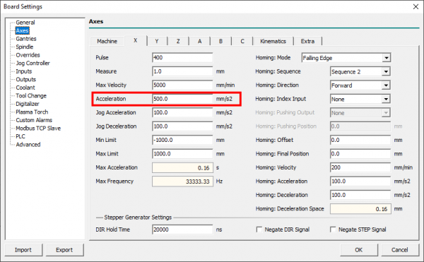
The “Acceleration” setting must be set to the maximum value allowed by the machine axis. This is not the tool acceleration value, it is only the value that can accelerate the axis. When a kinematics for example “AC Table” is set, the acceleration at the tool tip does not coincide with the acceleration of the single axis.
Some notes are divided according to the type of engine used:
2.1.1 Stepper motor
In this case, the acceleration must be set to the maximum value which avoids the loss of the step. There are various calculations in the literature or empirical tests to determine this value.
2.1.2 Brushless motor
In this case, the acceleration can be set to the value that generates a current in the motor equal to the nominal value (or to the limit value supplied by the manufacturer). If the motor has been oversized then it is necessary to set an acceleration value in accordance with the mechanical components used.
2.2 Control Mode G61 or G64
One key setting is the Control mode
2.2.1 G61
G61 means “Exact path mode” and forces the CNC to follow the programmed path using the look-ahead function to decrease the program duration. This is not the best choice if the goal is to have a constant tool path feed.
In fact, the CNC has the primary objective of being exact in the path. Only in some cases it will be possible for the CNC to have a non-zero speed at the end of a block. This possibility depends on the acceleration of the axes and the characteristics of the path.
There are two parameters that can be used in conjunction with G61 to change the behavior. They are the P503 and P504. But be careful because if you use values higher than 100% the acceleration provided to the axes will be higher than the value set in the axis settings. In general it could be a problem with stepper motors if the speed is high enough (risk of step loss).
2.2.2 G64
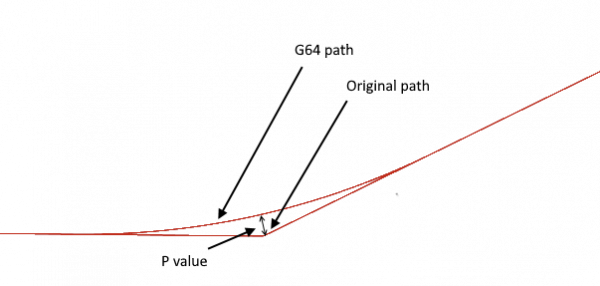
G64 is “Continuous path mode” that enables both look ahead and trajectory blending features to reach maximum speed performances.
This mode supports two optional parameters
P: Trajectory deformation/blending toleranceQ: Points removal threshold that can be used to decrease the number of points generated by the CAM
How to set the P parameter: it has to be set according to work precision. It is the distance between the corner start point and original block coordinate.
The higher P value, the more the CNC can keep the feed programmed through the various blocks.
If you are performing precision machining, it is generally a good choice to set a value higher than the machining tolerance and use the G9 code in the blocks where it is necessary that the trajectory be exact.
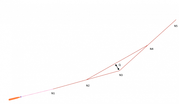
How to set the Q parameter: The Q parameter becomes important only if the CAM has generated a trajectory with many small blocks. It is important to indicate to the CNC which possibility is given to remove points because their removal does not generate a significant error.
Generally the Q parameter must be set according to the desired precision.
In this figure point N3 will be removed only if Q distance is less than Q parameter value.

2.3 Set interpolated motion dynamics G104
If you move the tool with an acceleration obtained using the maximum acceleration of each axis, you will certainly get a good machining time. But it is often not the best choice in terms of fluidity and mechanical stress. In fact, the CNC tries to reach the programmed feed at each block, creating strong accelerations in the machine. With the A D parameters associated with the G104 command we can set a tool acceleration value. Generally this value can be lower than the acceleration value of the axes and can also be dependent on the type of machining.
Example:
Board settings
- X axis acceleration set to 6000mm/s2
- Y axis acceleration set to 5000mm/s2
- Z axis acceleration set to 1000mm/s2
; Set interpolated motion dynamics to 800mm/s2
G104 A800 D900

G0 X0 Y0
G1 F1000
X100 Y100
M2
2.4 Use custom dynamics from G104 during fast motion P507
When you use a custom dynamics (G104) you probably want the CNC to use the maximum dynamics allowed by the axes during rapid movements so it is possible to move in the shortest time possible.
To do this, parameter P507 must be set to zero.

