AN018 - EtherCAT configuration nr.03
The purpose of this application note is to illustrate a simple guide for using RosettaCNC board B with EtherCAT command.
The proposed configuration is for demonstration purposes only.
1. What is the configuration nr.03
The configuration nr.03 consists of a series of HiWin ServoDrives E1 series. Up to 7 ServoDrives can be connected. The spindle is driven by analogic output. No EtherCAT Spindle device is provided for this configuration.
2. Necessary material
We need:
- A RosettaCNC board B purchased with EtherCAT option (see “Order Code” “Motor control type” at value E).
- From 1 to 7 ServoDrives purchased from RosettaCNC team (preconfigured to be ready to go)
3. Preliminary operations
- Install the latest version of the RosettaCNC software
- Close the application software. Open the application folder and replace the RosettaCNC1.ini with the attached.
- Open the “Board firmware manager” panel and start to download the EtherCAT firmware named RosettaCNC-BE-03.
- Open Board settings panel, press Import.. button and load the attached XML file.
At the end connect RosettaCNC software to the board. The software, only at the first run, takes some time (3-4 minutes) to generate a cache and be fast in subsequent runs. You can see the progress in the progress bar at the bottom in the RosettaCNC software.
4. Addressing
This configuration uses the Auto Increment Address of the EtherCAT slave device. Auto-increment addressing can be used to address each slave device is via its physical position in the communication ring. The first slave in the ring is X-axis, the second Y-axis, etc. This is the slave list:
- X-Axis
- Y-Axis
- Z-Axis
- A-Axis
- B-Axis
- C-Axis
- V-Axis
If the machine misses an Axis the physical cable must follow the next axis present.
5. Update EtherCAT ring configuration
Update Advanced Parameter from 121 to 129 according to ServoDrive presence.

Reboot system
6. Attached files
7. ServoDrive settings
Same servo drive settings are available on Advanced parameters. Other must be set by Thunder software.
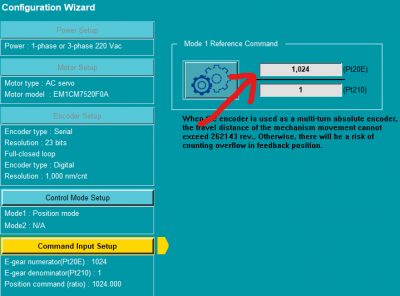
- To set the pulse revolution go to Thunder software, start Configuration Wizard and ser the values in the follow panel:
- If servo drive has absolute encoder it must be initialized after battery connection. To do this use the Thunder software and go to Tools→Absolute encoded initialization command.
- To reverse shaft direction use parameter PT000 bit 0. Take care that it is possible to change it only if the servo drive is not active. After changes turn on again.
- Output 5 is configured as BREAK, O4 as Alarm, O3 as DRIVE ready, O1 as Warning

8. Note
- Tested with model ED1F-EN-1022-A1-00 and firmware 2.10.6
- Depending on the machine's requirements, the STO safety signals must be wired correctly.
- When the encoder is used as a multi-turn absolute encoder, the travel distance of the mechanism movement cannot exceed 262143 rev. Otherwise, there will be a risk of counting overflow in feedback position.