IQ023 - Installation and Maintenance manual
Dear Customer,
Thank you for purchasing this product. RosettaCNC Board B is developed and manufactured with high standards to give high quality performance, ease of use and installation.
In case of difficulty during installation or use of the product, We recommend that you first consult the instructions or information on the www.rosettacnc.com site.
Need help?
Write in the forum on the www.rosettacnc.com site or send an email to the following address: support@rosettacnc.com, the RosettaCNC development team will be happy to answer you in a short time.
All rights reserved on this manual. No part of this document can be copied or reproduced in any form without prior written authorisation. RosettaCNC Motion® does not insure or guarantee its contents and explicitly declines all liability related to the guarantee of its suitability for any purpose. The information in this document can be changed without notice. RosettaCNC Motion® shall not be held liable for any error or omission in this document. RosettaCNC Motion® is a registered trademark.
Informations
 |
||||
| Document: | MIMIQ023 | |||
|---|---|---|---|---|
| Description: | Installation and Maintenance manual | |||
| Link: | http://wiki.rosettacnc.com/en/hardware:accessori:mimiq023 | |||
| Document release | Hardware Release | Description | Note | Data |
| 01 | 01 | New manual | / | 14/10/2021 |
1. Introduction
1.1 General description
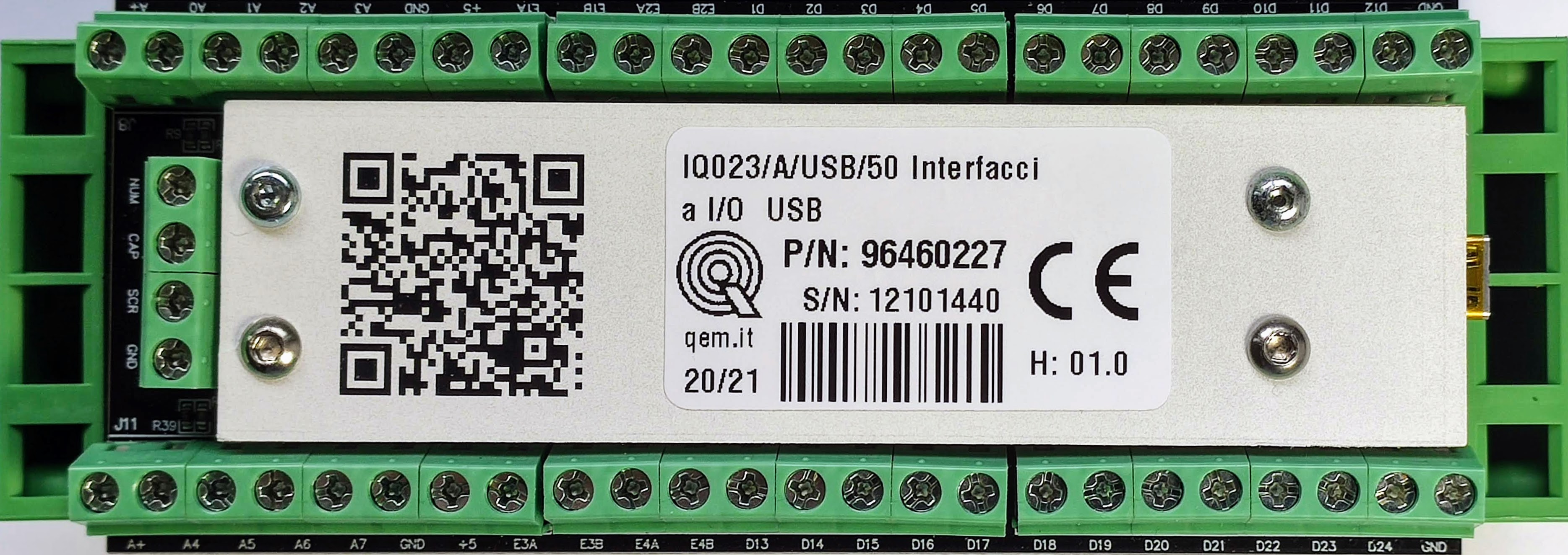
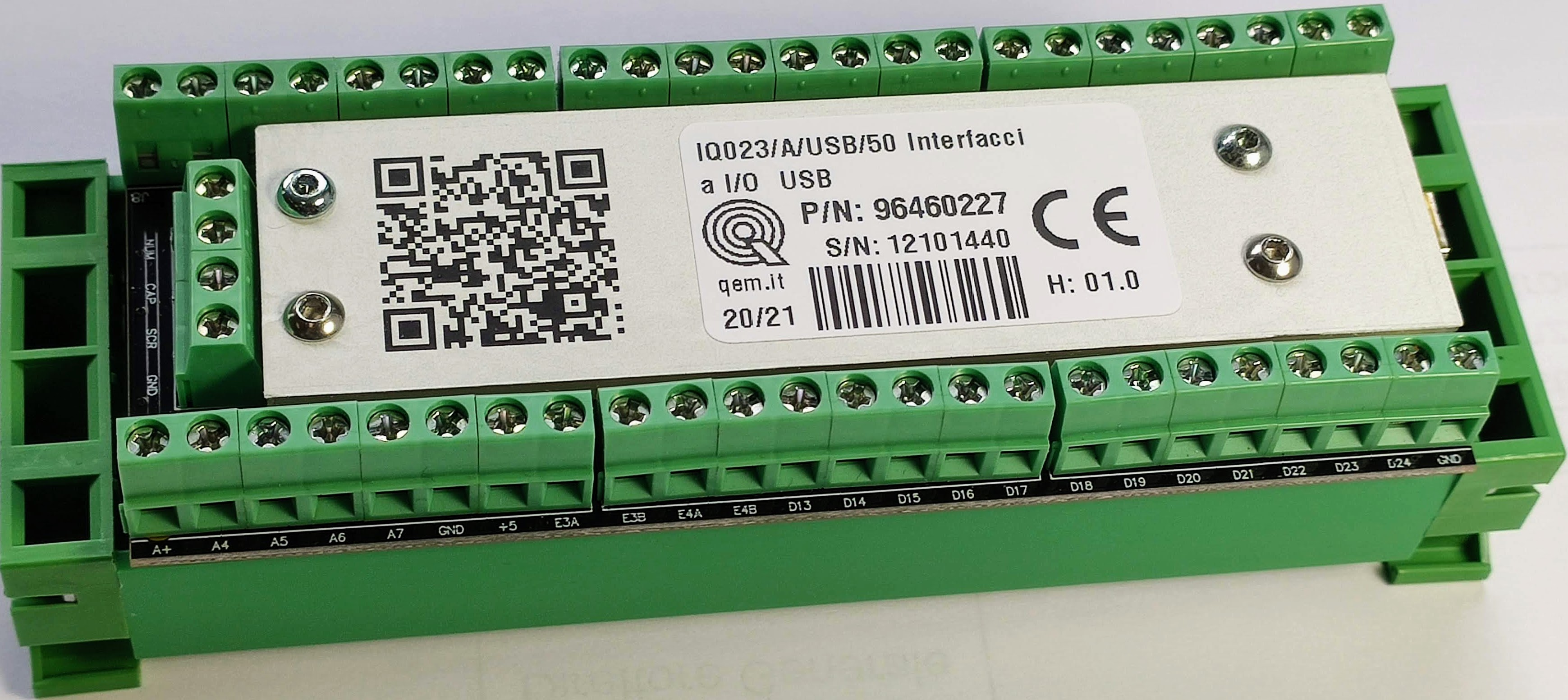
The IQ023 makes available on the Personal computer side 24 digital inputs, 8 analog inputs and 4 MPG inputs. It is a USB interface connected to the PC where the control software is installed. The accessory is indicated for providing I/O for commands on the pulpit.
1.2 Symbols used in the manual
Useful Information and tips
Warnings, failure to comply with these warnings may result in inappropriate operation or damage to the device
Potential danger and possible risk of injury
1.3 Package Contents
1.4 Mechanical installation
The fixing on the panel is carried out by attaching the instrument to an omega guide.
1.5 Product identification
With the product ordering code it's possible to obtain exactly the features.
Check that the product features match your needs.
1.5.1 Product label

- a - Ordering Code
- b - Week made: indicates the week and year of manufacture
- c - Part number: unique code that identifies an ordering code
- d - Serial number: product serial number, different for individual product
- e - Hardware release: version of hardware release
1.5.2 Ordering code
| Part number | Model | Features |
|---|---|---|
| 94460227 | IQ023/A/USB/50 | USB interface with 24 digiral inputs, 4 MPG and 8 analog inputs. |
1.5.3 Specification
| Description | Value |
|---|---|
| Weight (maximum hardware configuration) | 130g |
| Container material | PVC |
| Temperature range | 0 ÷ 50 ° C |
| Transport and storage temperature | -25 ÷ + 70 ° C |
| Relative humidity | 90% non-condensing |
| Altitude | 0 - 2000m a.s.l. |
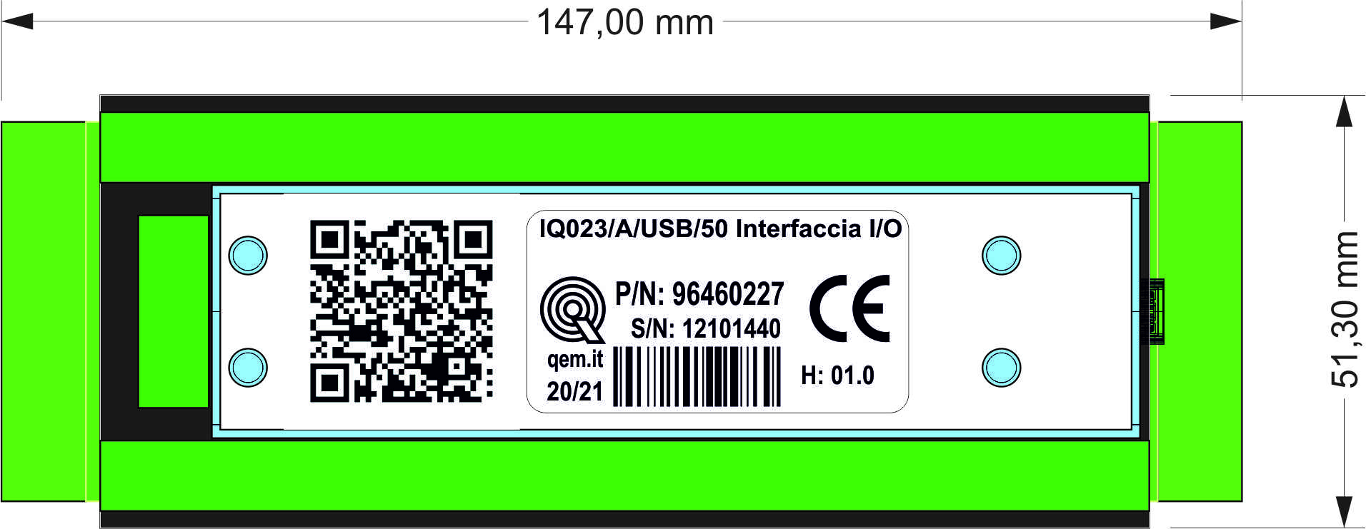
1.6 Mechanical dimensions
2. Connections
2.1 Power supply
The wiring must be carried out by specialized personnel and provided with appropriate anti-static measures.
Before handling the instrument, remove voltage and all parts connected to it.
To ensure with the CE compliance, The supply voltage must have a galvanic insulation of at least 1500 Vac.
The IQ023 is powered by the 5V of the USB port.
2.2 Terminals
| A+ | A0 | A1 | A2 | A3 | GND | +5 | E1A | E1B | E2A | E2B | D1 | D2 | D3 | D4 | D5 | D6 | D7 | D8 | D9 | D10 | D11 | D12 | GND |
| . | |||||||||||||||||||||||
 |
|||||||||||||||||||||||
| . | |||||||||||||||||||||||
| A+ | A4 | A5 | A6 | A7 | GND | +5 | E3A | E3B | E4A | E4B | D13 | D14 | D15 | D16 | D17 | D18 | D19 | D20 | D21 | D22 | D23 | D24 | GND |
2.2.1 Terminals description
| Symbol | Description |
|---|---|
| D1-D24 | Digital inputs NPN |
| E1A | Phase A of MPG 1 |
| E1B | Phase B of MPG 1 |
| E2A | Phase A of MPG 2 |
| E2B | Phase B of MPG 2 |
| E3A | Phase A of MPG 3 |
| E3B | Phase B of MPG 3 |
| E4A | Phase A of MPG 4 |
| E4B | Phase B of MPG 4 |
| A0-A7 | Analog inputs 0-3.3V, 16bit |
| GND | 0V for analog and digital inputs |
| A+ | 3.3Vdc out for analog inputs |
| +5 | 5Vdc out |
2.2.1.1 Digital inputs
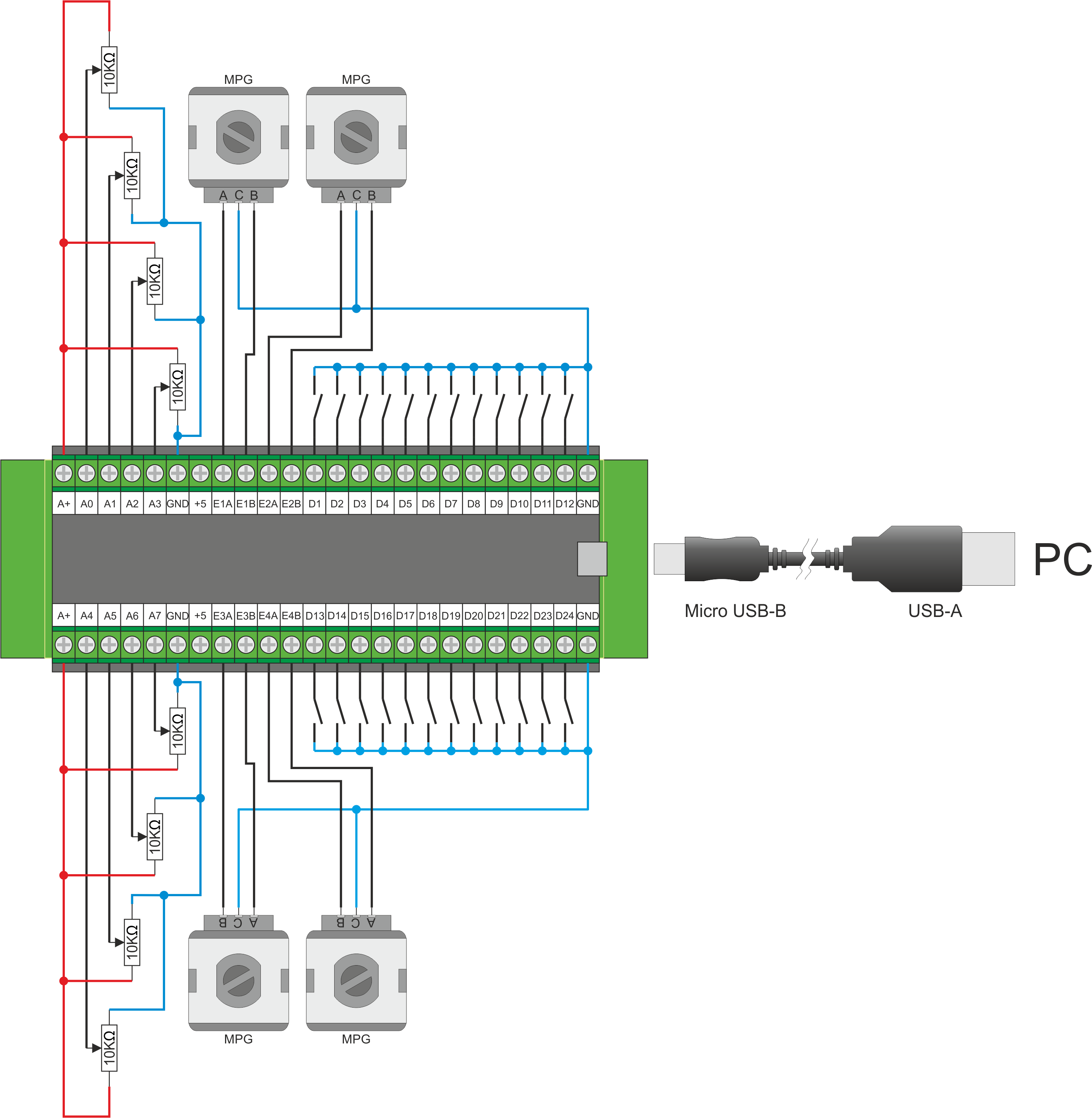
The digital inputs are of the NPN type and must be connected to 0V to activate them
2.2.1.2 Encoder inputs
The inputs of the encoder phases are of the NPN type and must be connected to 0V to activate them
2.2.1.3 Analog inputs
Analog inputs accept a voltage range from 0 to 3.3Vdc.
2.2.2 Connection examples
2.3 Usage Notes
- For resource mapping (digital inputs, analogue inputs and MPG) refer to the documentation of the board used.
- If MPGs are not used, Phase A and B signals can be used as digital inputs.
- In the digital inputs DO NOT connect devices that require NC logic but only NO.
2.4 Software settings
The accessory can be used with control software version 1.9.4 or later.
To enable use in the board settings, set the parameter marked in red as shown in the figure:
For resource mapping (digital inputs, analogue inputs and MPG) refer to the documentation of the board used.
3. Grants
We thank in advance all those who want to contribute to the improvement of this documentation by indicating inaccuracies or contents. Write to the address: support@rosettacnc.com


