RosettaCNC Handwheel A - Installation and Maintenance manual

Dear Customer,
Thank you for purchasing this product. This document collect all the necessary information for the installation and use of this accessory
Need help ?
Write in the Forum on the www.RosettaCNC.com site or send an email to the following address: support@rosettacnc.com, the RosettaCNC development team will be happy to answer you in a short time.
All rights reserved on this manual. No part of this document can be copied or reproduced in any form without prior written authorisation. RosettaCNC Motion® does not insure or guarantee its contents and explicitly declines all liability related to the guarantee of its suitability for any purpose. The information in this document can be changed without notice. RosettaCNC Motion® shall not be held liable for any error or omission in this document. RosettaCNC Motion® is a registered trademark.
Informations
| |
||||
| Document: | MIMROSETTACNCHANDWHEELA | |||
|---|---|---|---|---|
| Description: | Installation and Maintenance manual | |||
| Link: | http://wiki.rosettacnc.com/doku.php/en/hardware/rosettacncboard/mimrosettacnchandwheela | |||
| Document Release | Hardware Version | Description | Note | Date |
| 01 | 01 | / | 08/06/2017 | |
| 02 | 02 | / | 09/10/2018 | |
| 03 | 02 | Add description for RosettaCNC Board B | / | 12/12/2018 |
1. Introduction
1.1 General description
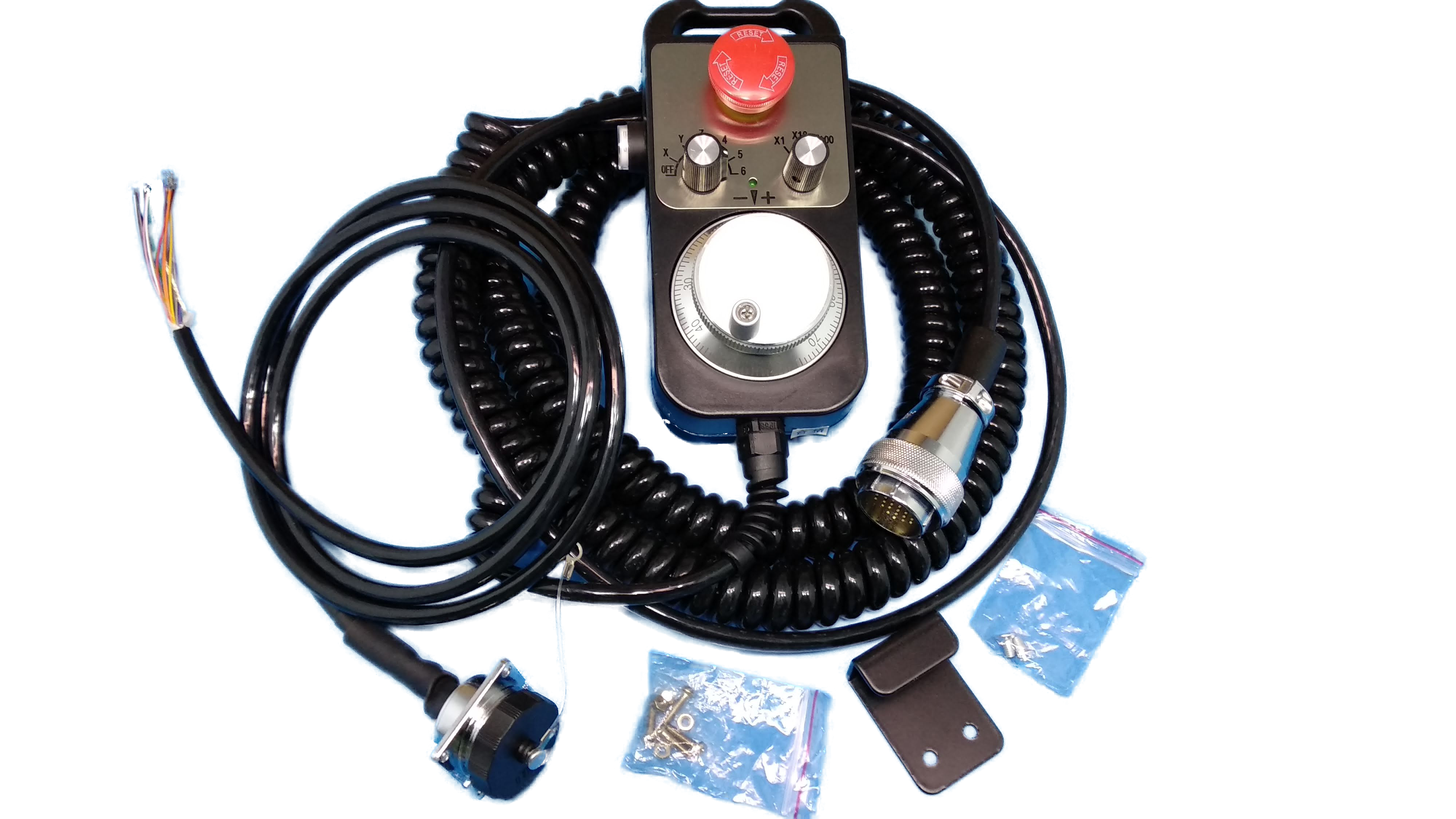
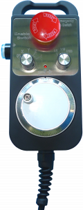
For the manual movements (jog) there is a RosettaCNC Handwell A accessory. It has an ergonomic shape that makes it easy to use And is contained in a sturdy anti-shock box. It is equipped with magnets that guarantee a reliable fixation, The electrical connection cable with the RosettaCNC controller It is equipped with a steel wire that increases its reliability and a removable connector with anti-vibration spring contacts.
Handwell A has :
- the enable command button
- the emergency button
- a selector for choosing the axis on which to act
- a three-position switch 1 – 1/10 – 1 /100 that defines the encoder unit of measurement.
- an encoder to execute the movement of the selected axis
Note:
- in automatic cycle, the encoder can change the value of the feed override.
- in manual, the enable command button can reset the selected axis.
1.2 Symbols used in the manual
Useful Information and tips.
Warnings, failure to comply with these warnings may result in inappropriate operation or damage to the device.^
Potential danger and possible risk of injury.^
1.3 Package Contents
- n.1 Handwheel
- n.1 wire
- n.1 Mounting bracket
- fixing screws
1.4 Product Identification
With the product ordering code it's possible to obtain exactly the features.
Check that the product features match your needs.
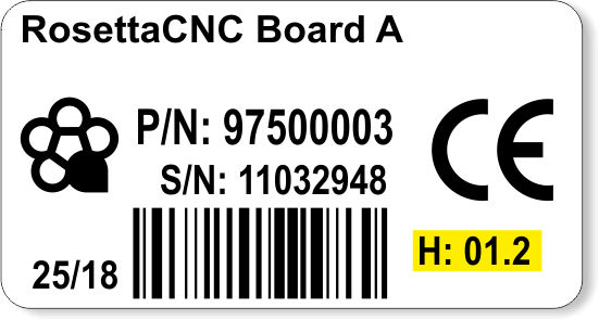
1.4.1 Product label
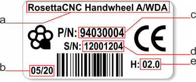
- a - Ordering Code
- b - Week made: indicates the week and year of manufacture
- c - Part number: unique code that identifies an ordering code
- d - Serial number: product serial number, different for individual product
- e - Hardware release: version of hardware release
1.4.2 Ordering code
The RosettaCNC HandWhell A product is available in the following version:
| Model | Part number | Description |
|---|---|---|
| 94030003 | RosettaCNC Handwhell A/CBL | Without connectors |
| 94030004 | RosettaCNC Handwhell A/WDA | With connectors ready to use for RosettaCNC Board A |
| 94030005 | RosettaCNC Handwhell A/WDB | With connectors ready to use for RosettaCNC Board B |
1.4.3 Specification
| Name | Description |
|---|---|
| Emergency button | contact normally closed |
| Enable button | enable Handwheel commands |
| Switch | 3 positions, 1 - 1/10 - 1/100 |
| Selector | 7 positions, OFF - X - Y - Z - 4 - 5 - 6 |
| Encoder | 100 divisions for revolution |
| Cable | with steel wire, length 1,7m (3m stretched) |
| Support | with magnets |
2. Mechanical installation
2.1 Drilling template
Drilling template for the panel connector.
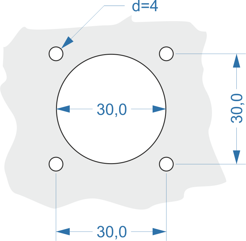
Dimensions in millimeters
3. Connections
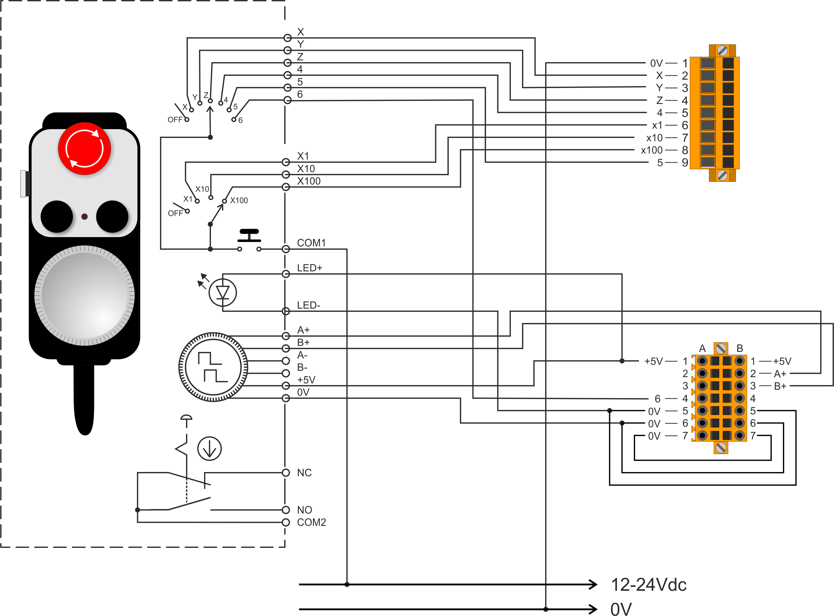
3.1 Cable description
3.1.1 Full cable
| Handwheel | Extension cord | ||||||||||
|---|---|---|---|---|---|---|---|---|---|---|---|
| Handwheel | Operation | Cable | Connector | Colore | PIN | PIN | Colore | Connector | Cable | Color | |
 | +5V | 21 terminals, 8mt long shielded spiral cable  | Weipu connectors WS28J20TS1 (male) 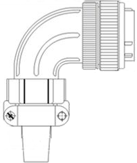 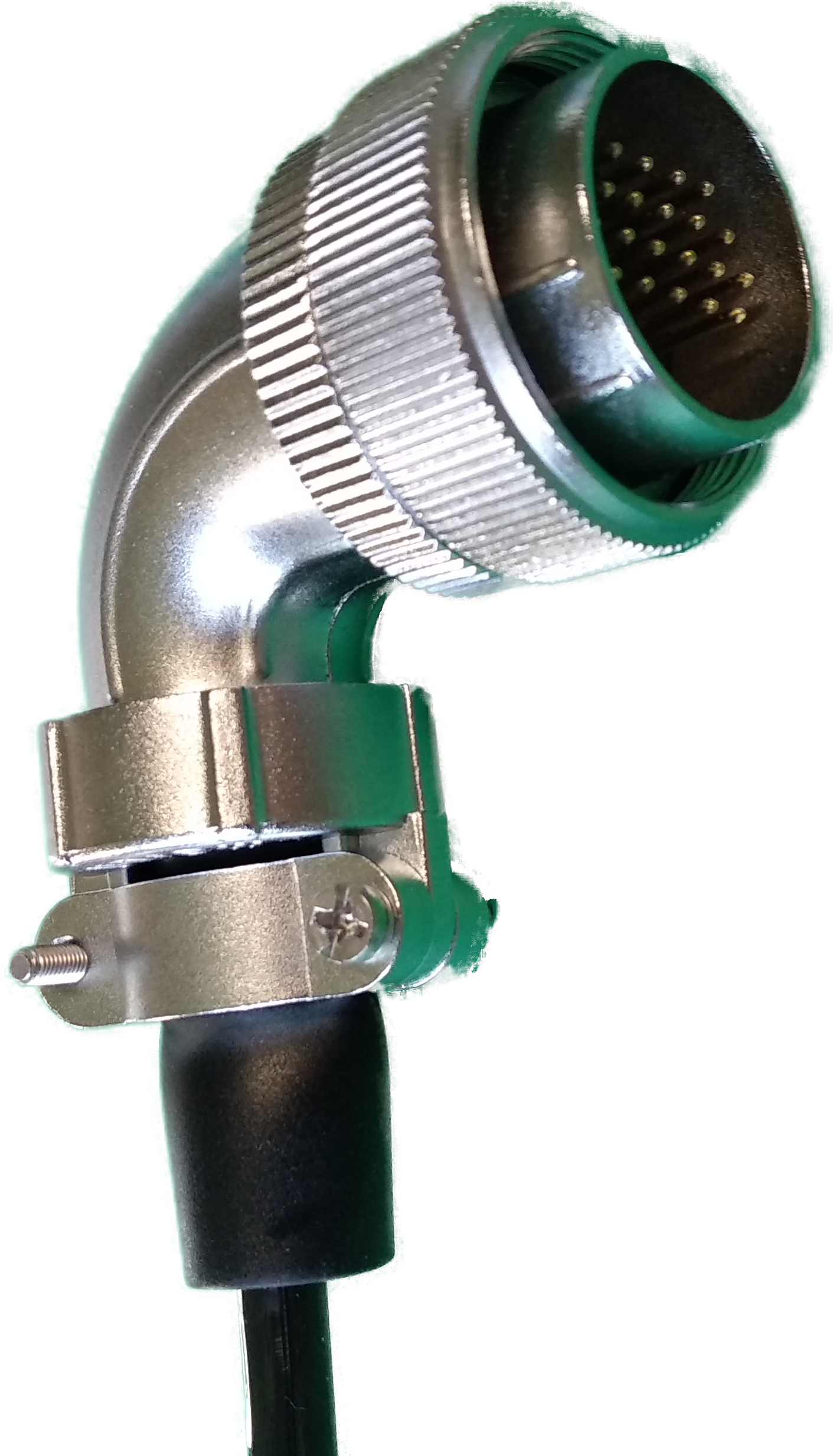 | red | 10 | 10 | | Weipu connectors WS28K20Zxx (femmina) 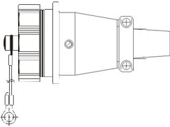 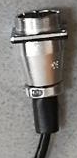 | 21 terminals, 1.5mt long shielded cable | red |
|
| 0V | black | 11 | 11 | | black |
||||||
| A | green | 12 | 12 | | green |
||||||
| B | white | 13 | 13 | | white |
||||||
| A- | violet | 15 | 15 | | violet |
||||||
| B- | violet/black | 16 | 16 | | violet/black |
||||||
| X | yellow | 1 | 1 | | yellow |
||||||
| Y | yellow/black | 2 | 2 | | yellow/black |
||||||
| Z | brown | 3 | 3 | | brown |
||||||
| 4 | brown/black | 4 | 4 | | brown/black |
||||||
| 5 | pink | 19 | 19 | | pink |
||||||
| 6 | pink/black | 20 | 20 | | pink/black |
||||||
| X1 | grey | 5 | 5 | | grey |
||||||
| X10 | grey/black | 6 | 6 | | grey/black |
||||||
| X100 | orange | 7 | 7 | | orange |
||||||
| COM1 | orange/black | 14 | 14 | | orange/black |
||||||
| COM2 | blue | 17 | 17 | | blue |
||||||
| NC | blue/black | 18 | 18 | | blue/black |
||||||
| LED+ | green/black | 9 | 9 | | green/black |
||||||
| LED- | white/black | 8 | 8 | | white/black |
||||||
| red/black | | red/black |
|||||||||
3.1.2 Terminals only
| Encoder | |
|---|---|
| Color | Function |
| red | +5V |
| black | 0V |
| green | A |
| white | B |
| violet | A- |
| violet/black | B- |
| Axis selector and multiplier | |
| yellow | X |
| yellow/black | Y |
| brown | Z |
| brown/black | 4 |
| pink | 5 |
| pink/black | 6 |
| grey | X1 |
| grey/black | X10 |
| orange | X100 |
| orange/black | COM1 |
| Estop | |
| blue | COM2 |
| blue/black | NC |
| LED | |
| green/black | LED+ |
| white/black | LED- |
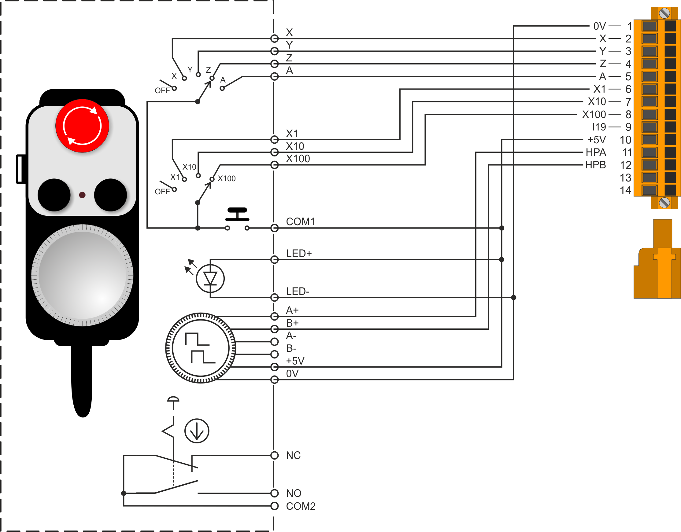
3.2 Connections with RosettaCNC Board A
This product is compliant only with RosettaCNC Board A hardware version 1.2 or greater.
| Handwheel | Connector CN11 on RosettaCNC Board A | ||
|---|---|---|---|
 | black | 1 | 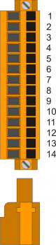 |
| white/black |
|||
| yellow | 2 | ||
| yellow/black | 3 | ||
| brown | 4 | ||
| brown/black | 5 | ||
| grey | 6 | ||
| grey/black | 7 | ||
| orange | 8 | ||
| 9 | |||
| red | 10 | ||
| orange/black |
|||
| green/black |
|||
| green | 11 | ||
| white | 12 | ||
| 13 | |||
| 14 | |||
| blue | To be connected in series to the emergency stop circuit | ||
The following wires remain disconnected:
 violet
 violet/black
 pink
pink
 pink/black
3.2.1 Installation
To connect the handwheel to the RosettaCNC board A, insert the connector into the CN11 as shown in the picture:
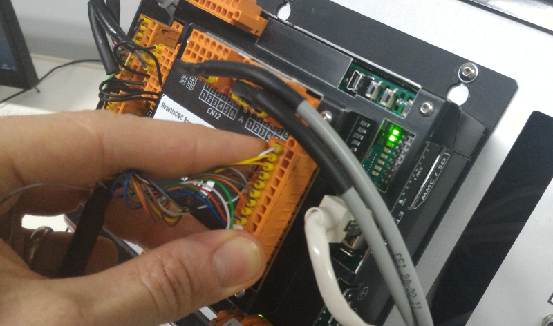
Picture 1. Handwheel Installation
Check the emergency button connection in accordance with the safety circuit of the machine.
For examples of connection of emergency circuits see the product manual RosettaCNC Board A.
3.3 Connections with RosettaCNC Board B
| Handwhell | Connector CN17 on RosettaCNC Board B | ||
|---|---|---|---|
| | red | 1A |  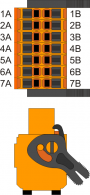
Connect: |
| green/black |
|||
| green | 2B | ||
| white | 3B | ||
| pink/black | 4A | ||
| black | 7A | ||
| white/black | 7B | ||
| Connector CN19 on RosettaCNC Board B | |||
| yellow | 2 |  |
|
| yellow/black | 3 | ||
| brown | 4 | ||
| brown/black | 5 | ||
| grey | 6 | ||
| grey/black | 7 | ||
| orange | 8 | ||
| pink | 9 | ||
| orange/black | To be connect at +24Vdc | ||
| blue | To be connected in series to the emergency stop circuit | ||
The following wires remain disconnected:
- violet
- violet/black
3.3.1 Installation
To connect the handwheel to the RosettaCNC board B, insert the connectors CN17 and CN19 as shown in the picture:
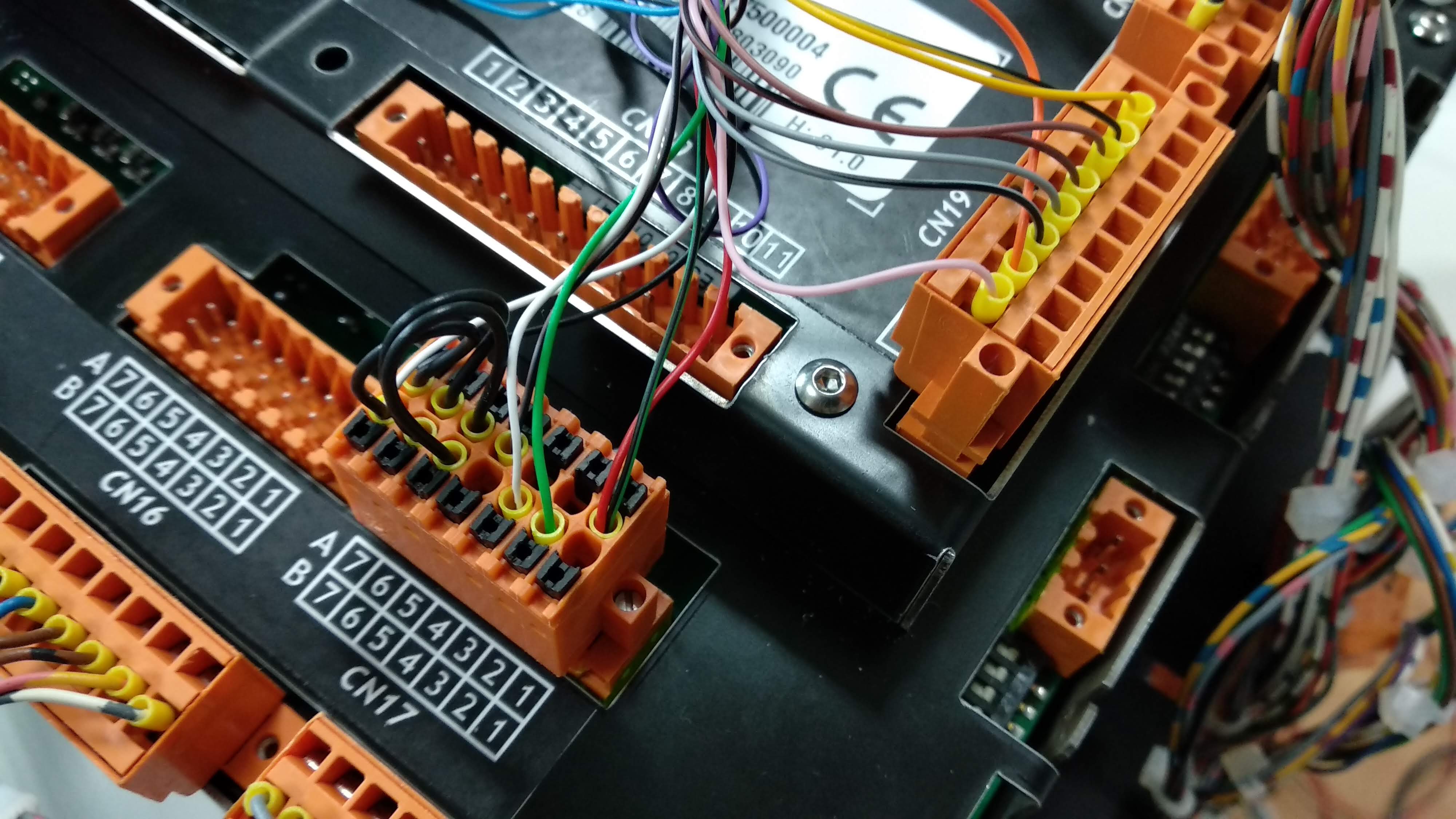
Figure 2. Installation
Check the emergency button connection in accordance with the safety circuit of the machine.
For examples of connection of emergency circuits see the product manual RosettaCNC Board B.
4. Settings
To use the handwheel, you must set the highlighted values in the followinf picture (In the “RosettaCNC board settings” Panel):
 |
5. Previous hardware versions
Below are links to consult the previous hardware versions of the product.
| Modello | Part number |
|---|---|
| Hardware version 01 | User Manual |
6. Acknowledgement
All those who want to contribute to the improvement of this documentation are in advance thanks to the reporting inaccuracies or incorrect content. Write to the address: support@rosettacnc.com