This is an old revision of the document!
AN002 - Sample diagrams for connecting to AEC drivers
Informations
| |
||||
| Document: | AN002 | |||
|---|---|---|---|---|
| Description: | Sample diagrams for connecting to AEC drivers | |||
| Link: | http://wiki.rosettacnc.com/doku.php/en/appnote:an002 | |||
| Document Release | Hardware Release | Description | Note | Date |
| 01 | 01 | Sample diagrams for connecting with AEC stepper drivers. | / | 05/06/2017 |
Table of Contents
1. Description
The following manual, shows with some sample diagrams, the connection between RosettaCNC and 4 AEC stepper drivers.
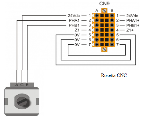
Also indicated are the connections with the electronic handwheel and the MPGA encoder.
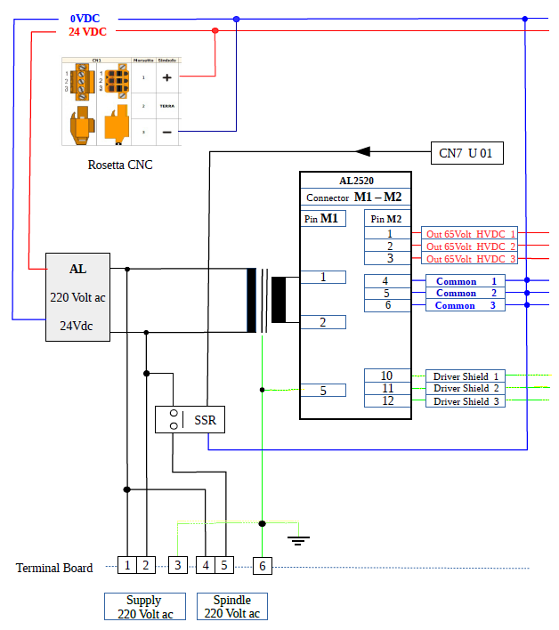
2. Power Section
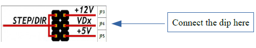
3. Motor driver section
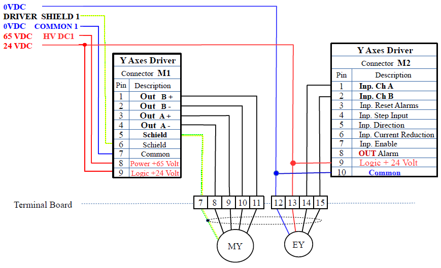

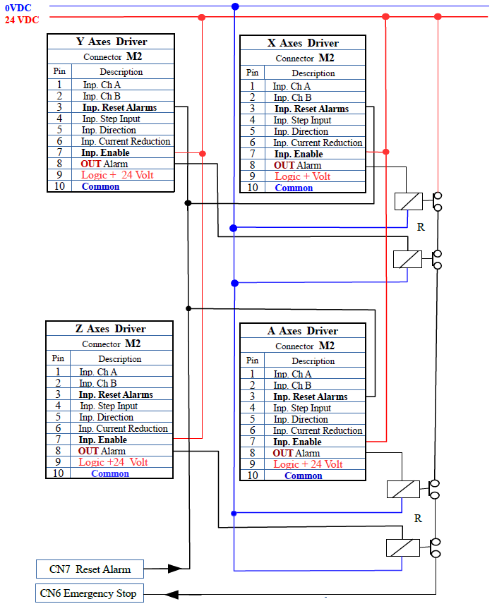
4. Y X axes controls motor driver section

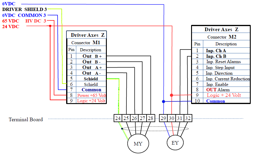
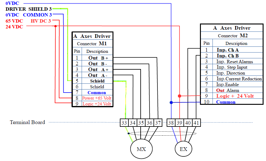
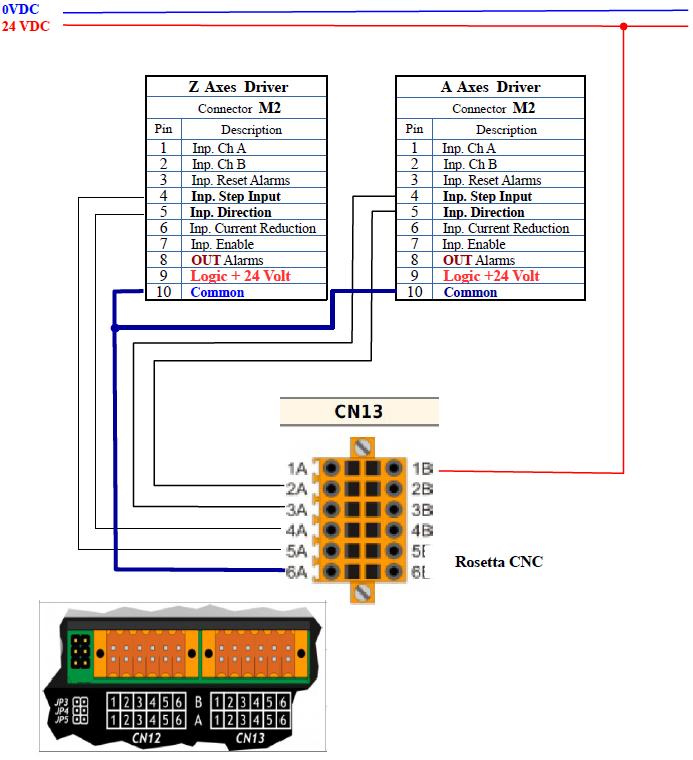
5. Z A axes controls motor driver section
6. Alarms and alarm reset section
7. RossettaCNC input section
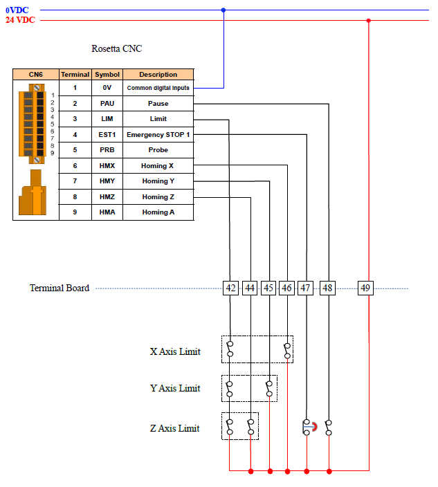
8. RossettaCNC input (with proximity homing) section
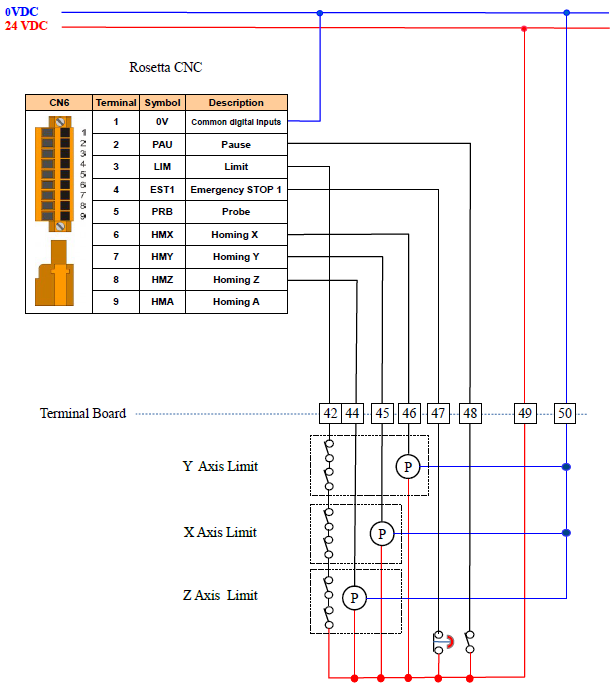
![]() = Proximity switch, type PNP, normally open, with shielded cable
= Proximity switch, type PNP, normally open, with shielded cable
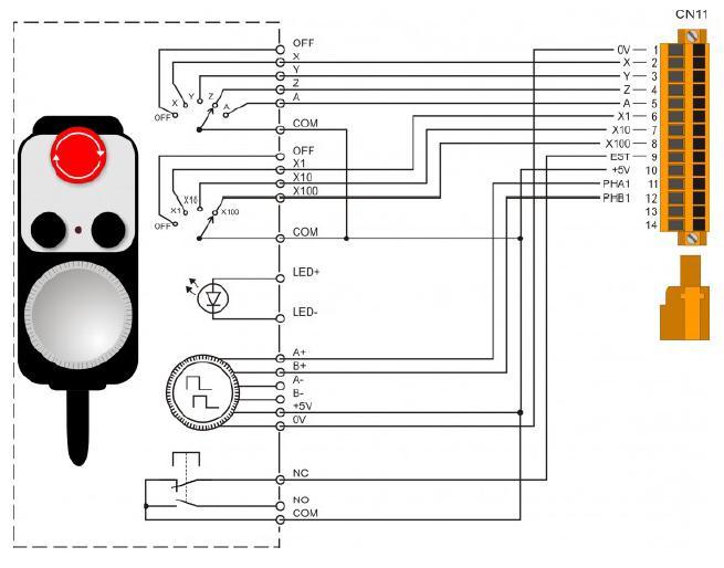
9. Handwheel section
10. Override section
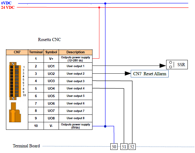
11. RosettaCNC outputs section
12. Legend
| Type | Code | Description | |
|---|---|---|---|
| AL | Logic Supply Input 220 Volt ac, Output 24 Volt dc, 2 Ampere |
||
| AL2520 | Driver Power Supply | ||
| Driver Axes | SMD1104LS | ||
| SSR | Static relay 220 Volt ac 25 Ampere | ||
| RosettaCNC | RosettaCNC Board A/4 | 97500003 | CNC Control |
| Handwheel | 94030001 | ||
| MPGA | 22100045 | Mechanical rotary encoder | |
| R | 24 Volt coil relay, with gold contacts |