RosettaCNC Board A - Installation and Maintenance manual

Dear Customer,
Thank you for purchasing this product. RosettaCNC Board A is developed and manufactured with high standards to give high quality performance, ease of use and installation.
In case of difficulty during installation or use of the product, We recommend that you first consult the instructions or information on the www.rosettacnc.com site.
Need help ?
Write in the forum on the www.rosettacnc.com site or send an email to the following address: support@rosettacnc.com, the RosettaCNC development team will be happy to answer you in a short time.
All rights reserved on this manual. No part of this document can be copied or reproduced in any form without prior written authorisation. RosettaCNC Motion® does not insure or guarantee its contents and explicitly declines all liability related to the guarantee of its suitability for any purpose. The information in this document can be changed without notice. RosettaCNC Motion® shall not be held liable for any error or omission in this document. RosettaCNC Motion® is a registered trademark.
Informations
| |
||||
| Document: | MIMROSETTACNCBOARDA | |||
|---|---|---|---|---|
| Description: | Installation and Maintenance manual | |||
| Link: | http://wiki.rosettacnc.com/doku.php/en:hardware:rosettacncboard:mimrosettacncboarda | |||
| Document release | Hardware Release | Description | Note | Date |
| 1 | 01 | / | 30/05/2017 | |
| 2 | 01 | Fix user inputs pin. Add user inputs nr 7 and 8 | / | 07/07/2017 |
| 3 | 01 | New PRB input description | / | 06/12/2017 |
| 4 | 01 | Complete some instructions for STEP DIR outputs | / | 02/07/2018 |
| 5 | 01.2 | Corrected the electrical characteristics of CN11 and CN3. some stylistic improvements | / | 12/12/2018 |
| 6 | 01.2 | Added new features for RosettaCNC software version 1.5 | / | 25/01/2019 |
| 7 | 01.2 | New order code | / | 29/04/2019 |
| 8 | 01.2 | Update order code | / | 31/07/2019 |
| 9 | 01.2 | New CN11 description for RosettaCNC software version 1.6 | / | 31/07/2019 |
| 10 | 02.0 | New Optional CN4/CN10 description and English translation fixes | / | 08/02/2025 |
| 11 | 02.0 | Add new order code with “Jerk control” feature | / | 05/06/2020 |
| 12 | 02.0 | Add new User Inputs and virtual Inputs Outputs. | / | 30/04/2021 |
| 13 | 04.0 | Added Infos for new hardware release 4.0 | / | 12/12/2022 |
| 14 | 05.0 | Added options 4 and 5 in the Expansion I/O field | / | 26/07/2024 |
1. Introduction
1.1 General description
RosettaCNC Board A is an ETHERNET motion controller that manages up to 4 interpolated axes. The ETHERNET port (instead of USB) ensures fast and secure transmission thanks to the protocol and at the e galvanic insulation with the PC connection.
Does not require the use of external electronic parts or protectors. The power supply is integrated and protected, The inputs and outputs are equipped with opto-insulator that guarantee, together with the metal container, high resistance to electromagnetic interference. The outputs are protected from short circuits and allow you to directly connect inductive loads (relays or solenoid valves), without having to add external components.
The control outputs of STEP/DIR type are generated by a powerful FPGA That allows to reach operating frequencies of 2MHz (with stable duty cycle at 50%) making it possible to use both step-by-step drives and servo drives.
Rosetta CNC Board commands the axes using a look ahead that allows you to achieve high interpolation speeds.
The product can possibly be equipped with a handwheel, supplied already complete with connector, alternatively, it makes available inputs for the jog connection joystick type and other useful control signals.
Rosetta CNC Board is equipped with removable spring connectors to allow quick wiring, highly reliable and free to vibrations.
1.2 Symbols used in the manual
Useful Information and tips.
Warnings, failure to comply with these warnings may result in inappropriate operation or damage to the device.
Potential danger and possible risk of injury.
1.3 System composition
RosettaCNC Motion® is a system composed of the following elements:
- RosettaCNC Board A which is the motion controller described in this document.
- RosettaCNC software, a complete Windows® application to configure, monitor, and execute G codes.
- THe RosettaCNC Handwheel A accessory, a practical and economical handwheel.
- The RosettaCNC MPG A accessory, is a rotary device to change the override.
If using RosettaCNC Board A hardware release 4.0 or later you must use control software version 1.11 or higher.
1.4 Product Compliance
CE Marking and reference standards
The controller has been designed for industral environments in conformity to EC directive 2004/108/CE.
- EN 61000-6-4: Electromagnetic compatibility - Generic standard on emission for industrial environments
- EN55011 Class A: Limits and measurement methods
- EN 61000-6-2: Electromagnetic compatibility - Generic standard on immunity for industrial environments
- EN 61000-4-3: Immunity to radiated, radio-frequency electromagnetic field
- EN 61000-4-4: Electrical fast transients
- EN 61000-4-5: Surge immunity
- EN 61000-4-6: Conducted disturbance induced by radio-frequency
- Moreover the product is conform to the following standards:
- EN 60068-2-1: Environmental testing: Cold
- EN 60068-2-2: Environmental testing: Dry heat
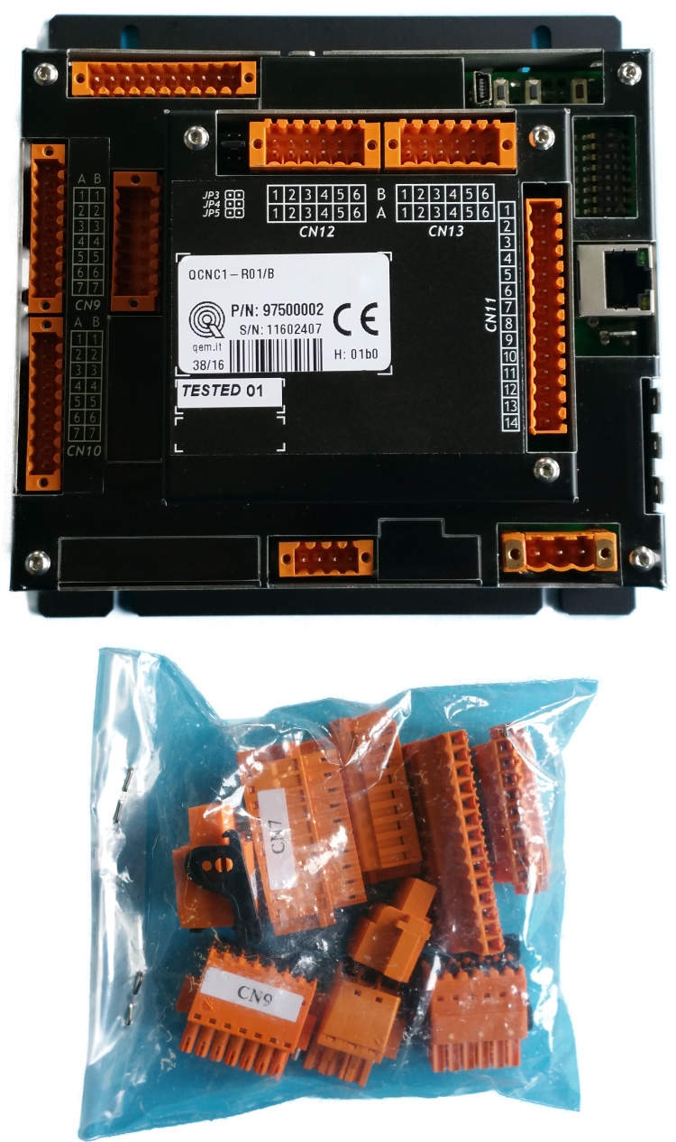
1.5 Package Contents
- n.1 RosettaCNC Board
- n.1 Pack of spring terminals
1.6 Product identification
With the product ordering code it's possible to obtain exactly the features.
Check that the product features match your needs.
1.6.1 Product label
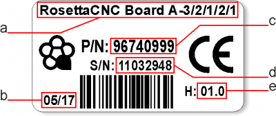
- a - Ordering Code
- b - Week made: indicates the week and year of manufacture
- c - Part number: unique code that identifies an ordering code
- d - Serial number: product serial number, different for individual product
- e - Hardware release: version of hardware release
1.6.2 Ordering code
| Model | - | Features | |||||||||||||
| RosettaCNC A | - | 3 | / | 0 | / | 0 | / | 1 | / | 1 | / | 1 | - | 001 | |
|---|---|---|---|---|---|---|---|---|---|---|---|---|---|---|---|
| Customization Code. (omitted if no customization is present) | |||||||||||||||
| Functions “Group B”. 0 = No Functions Enabled; 1 = Laser Acquisition; 2 = internal THC; | |||||||||||||||
| Functions “Group A”. 0 = No Functions Enabled; 1 = RTCP; 2 = Jerk control; 3 = RTCP + Jerk control; | |||||||||||||||
| Remote Communication. 0 = No communcation; 1 = OPC; 2 = OPC + RosettaCNC Data Exchange 4.0; | |||||||||||||||
| I/O Expansion. 0 = Not present; 1 = Base Expansion; 2 = Analog Inputs Expansion; 3 = Full Expansion; 4 = Full Expansion + RS485 Serial; 5 = Full Expansion + RS485 Serial and CANbus | |||||||||||||||
| Max step frequency for axis. 0 = 125 KHz; 1 = 200Khz; 2 = 300Khz; 3 = 500Khz; 4 = 1Mhz; 5 = 2Mhz; | |||||||||||||||
| Number of Axis. 3 = 3 axis; 4 = 4 axis; | |||||||||||||||
| Controller Model. RosettaCNC A = Board A Controller Board | |||||||||||||||
1.6.3 Normally available codes
| Part number | Model | Features |
|---|---|---|
| 97500012 | RosettaCNC A - 4/1/0/0/0 | 4 axes, max step freq 200 KHz |
| 97500007 | RosettaCNC A - 4/2/0/0/0 | 4 axes, max step freq 300 KHz |
| 97500009 | RosettaCNC A - 4/2/0/1/0 | 4 axes, max step freq 300 KHz, OPC-UA server |
| 97500010 | RosettaCNC A - 4/3/0/0/0 | 4 axes, max step freq 500 KHz |
| 97500011 | RosettaCNC A - 4/4/3/1/1 | 4 axes, max step freq 1 MHz, OPC-UA server, I/O expansion, RTCP, Laser Acquisition |
Starting from May 2019 the Part Number 97500003 “4 axis version” is replaced by the new code 97500007 .
1.6.4 Specification
| Description | Value |
|---|---|
| Power supply | 24VDC |
| Maximum absorption | 5W |
| Axis number | 3 or 4 1) |
| Digital inputs | 19 or 21 2) (18 always available, 1 depending by “Jog Controller Type” parameter, remaining 2 on I/O Expansion) |
| Handwheel interface | 4-Axis Selector x1-x10-x100 Selector Emergency button |
| Probe inputs | 1 |
| Tachimeter inputs | 1 3) |
| EXTRA digital inputs | 10 4) |
| Analog inputs | 3 5) |
| Digital outputs | 8 o 16 6) |
| Analog outputs | 1 |
| Axis control type | STEP/DIR |
| PC Communication | Ethernet 10/100Mb |
| Temperature range | 0°C to +50°C |
| MPG inputs | 2 or 3 7) (MPG1 shared with HandWheel) |
| Enclosure Protection Degree | IP20 (as from EN-60529 normative) |
2. Safety
RosettaCNC Board it's powered in low voltage, 24VDC, the I/O line are opto-insulated and the PC connection is galvanically isolated, therefore the device is not a direct threat to the health and life of the user.
The design of a complete control system (electric panel), should draw attention to different aspects of, so that the whole machine system does not become a danger during the use.
It's good practice to always use NC contacts for the limit switches and for the emergency button So that a wiring error or a wire disconnection always lead to machine shutdown.
Special attention must be paid to the emergency stop circuit: The control system must be designed in such a way the that when you press the button for emergency stop, the machine immediately interrupts the movement of all axes. You should also consider the possibility of failure of particular components of the system, as the main controller, or the axes control units.
The safety of the machine is never the responsibility of the RosettaCNC Board Controller
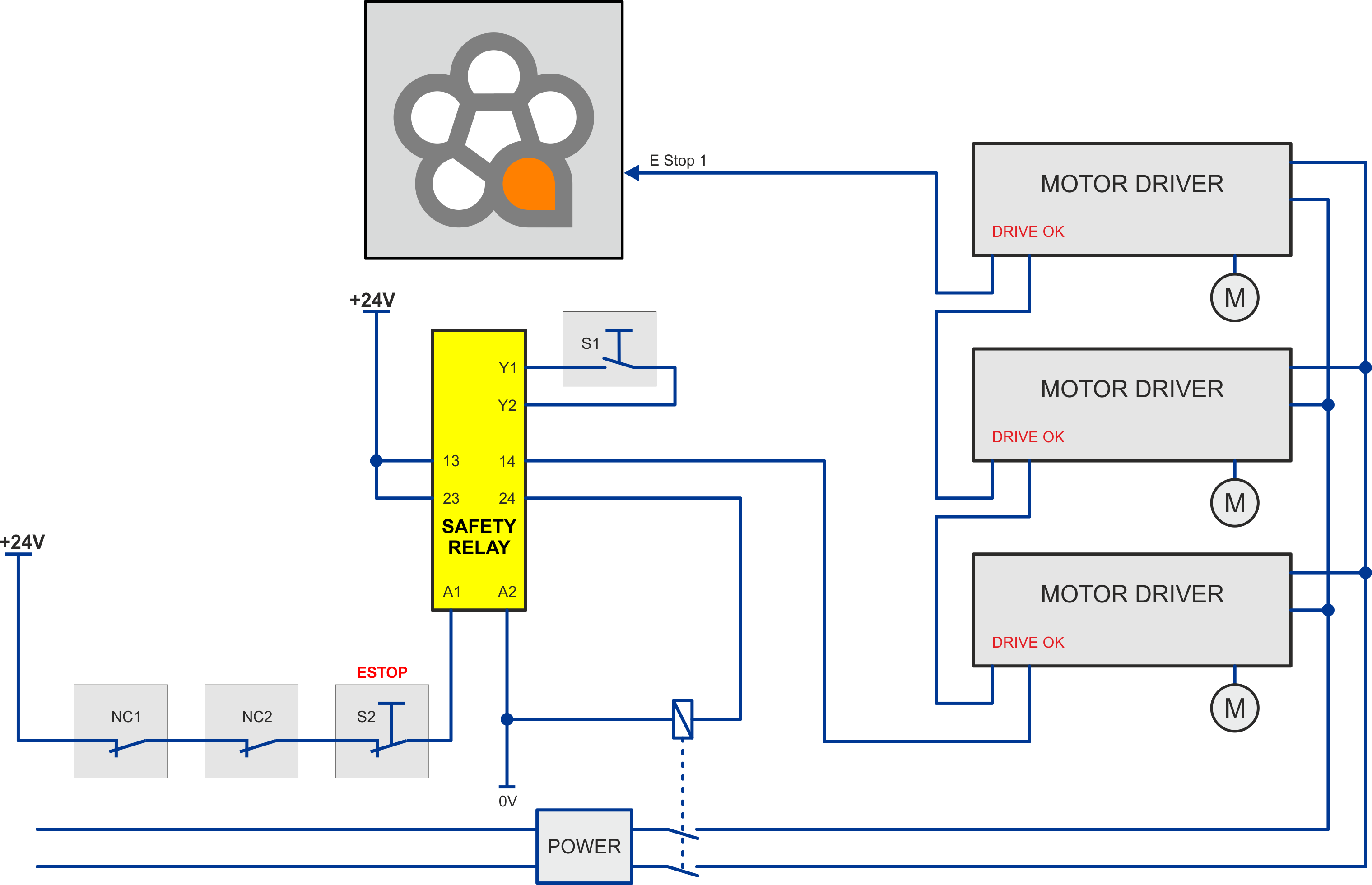
Here are two examples of connection. The first uses the Safe Torque Off (STO) input Present in drives.
The second uses a safety device to control the chain of emergency signals.
Both are only example schemes and each installer must then design its own scheme suitable for the machine according to the regulations.

In the below picture, is used a safety device Pilz model PNOZ X7. The emergency button, and possibly other alarm signals (safety barriers, crankcase opening, etc.) must be connected to the input circuits. An output must be connected to the EST1 input of RosettaCNC Board And in series also the drive ok outputs. The other exit of the safety module must be used to stop power to drives.
S1 is the Restore button.
S2 is the stop button in emergency.
3. Mechanical Installation
3.1 Mechanical dimensions
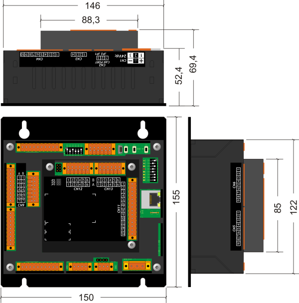
Dimensions in mm
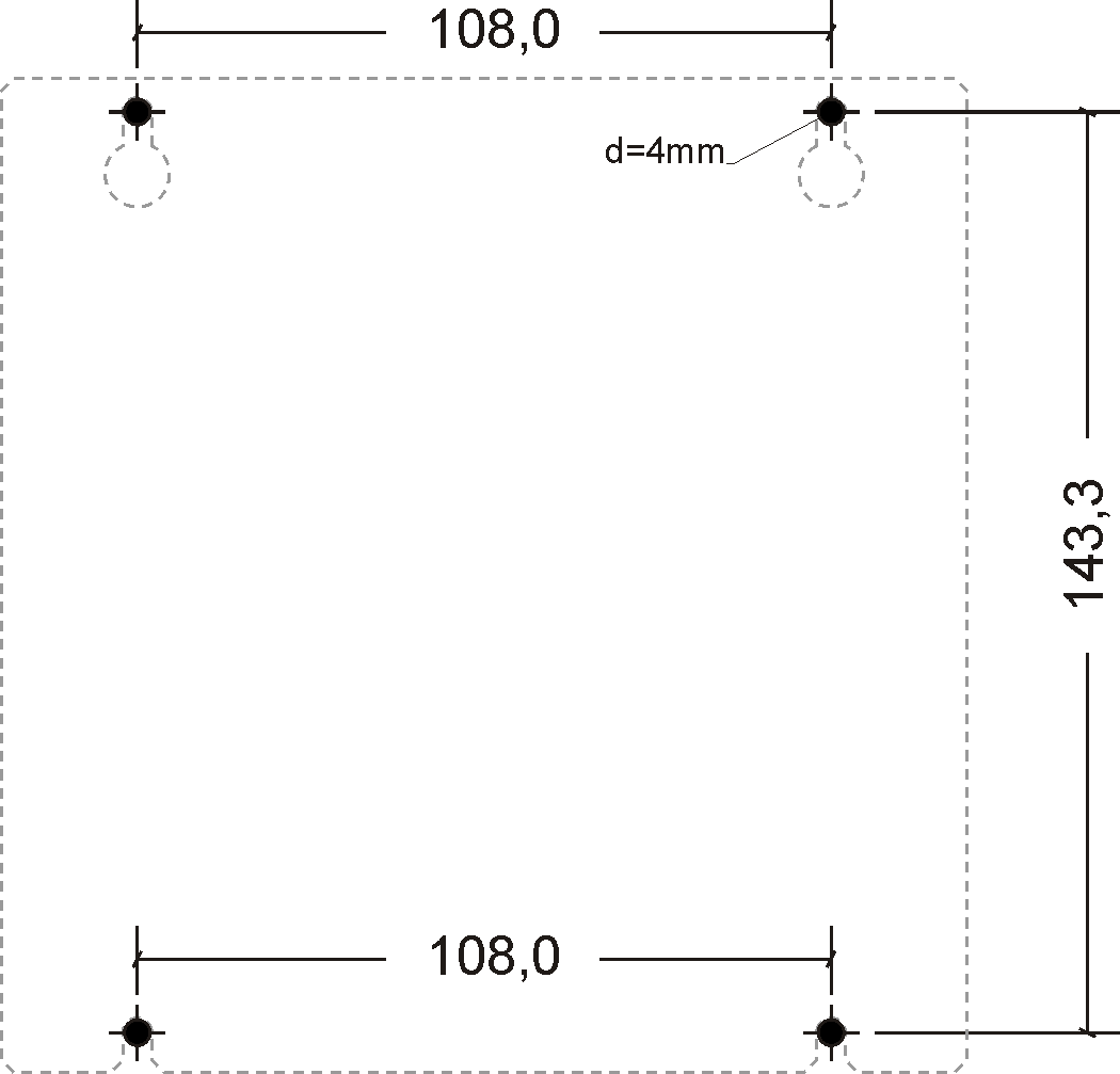
3.2 Hole template
4. Connectors
For information about the usable cable sections and the used connectors, see the Application Note AN001
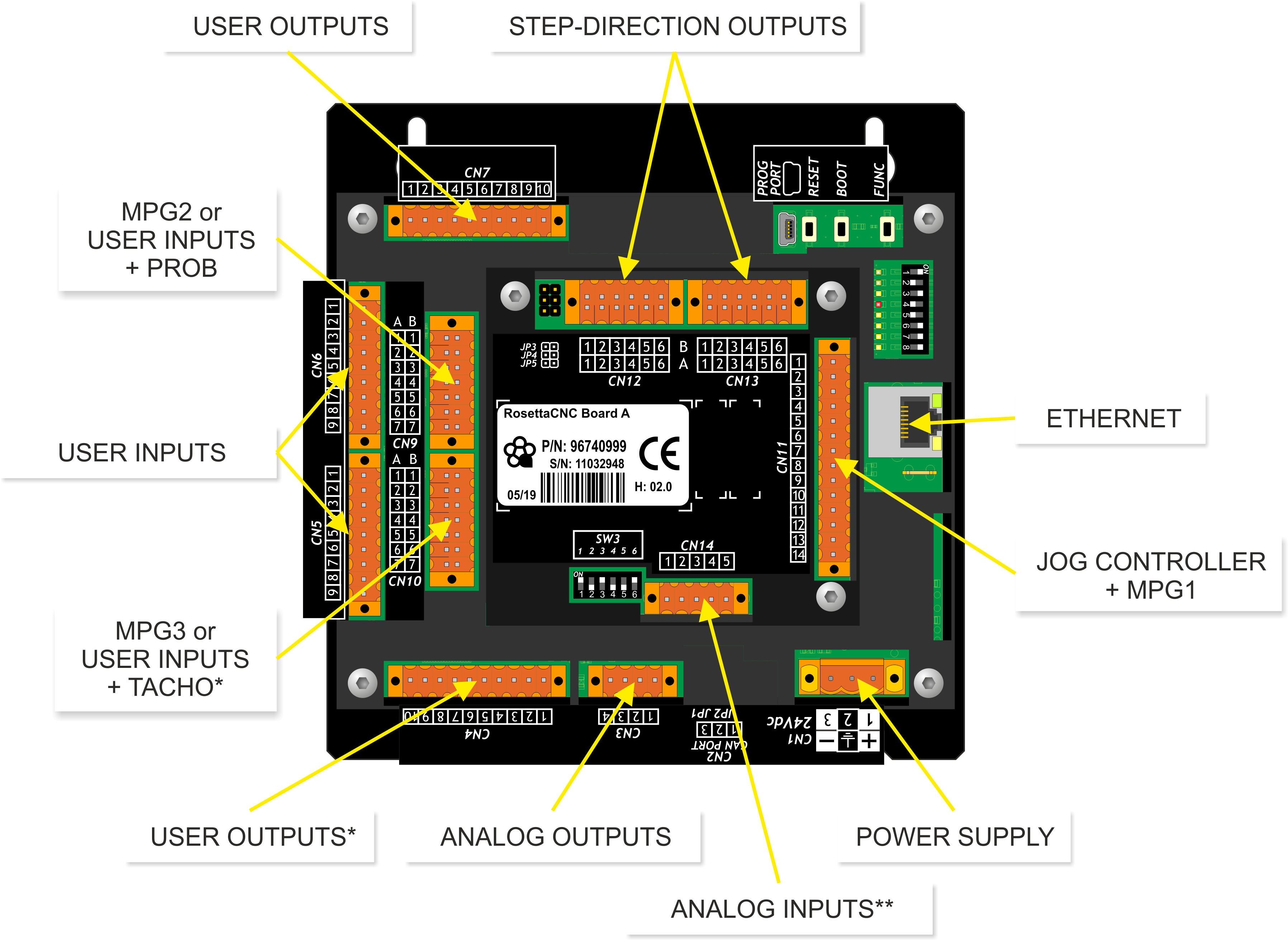
* Connectors CN4 and CN10 are available only with field I/O Expansion = 1 o 3, in order code.
** Connector CN14 is available only with field I/O Expansion = 2 or 3, in order code.
4.1 Power supply
The wiring must be carried out by specialized personnel and provided with appropriate anti-static measures.
Before handling the instrument, remove voltage and all parts connected to it.
To ensure with the CE compliance, The supply voltage must have a galvanic insulation of at least 1500 Vac.
| Available power supplies | 24 Vdc |
|---|---|
| Valid range | 22 ÷ 27 Vdc |
| Max. absorption | 5W |
Connector
| CN1 | Terminal | Symbol | Description | |
|---|---|---|---|---|
 | 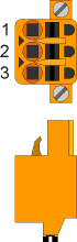 | 1 | | Positive power supply |
| 2 | GROUND | Ground-PE (signals) | ||
| 3 | | 0V power supply | ||
Connection examples
Is prescribed the use of insulated power supply with 24Vdc output complies with EN60950-1.
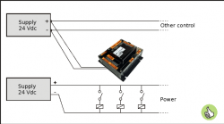 | Use two separate power supplies: one for the control part and one for the power part |
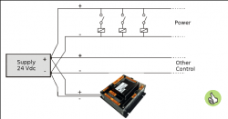 | In the case of a single power supply, Use two separate lines: one for control and one for power |
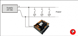 | Do not use the same lines as the power part |
4.2 Serial Connections
4.2.1 ETHERNET port
| ETHERNET PORT | Description |
|---|---|
 | RJ45 connector. LED: * LINK: green led = connected cable (the LED on indicates that the cable is connected to both sides) * DATA: yello led = data exchange (the blinking LED indicates the data exchange between the connected devices) |
4.3 Digital inputs
The digital inputs called “User input” can be configured by the RosettaCNC software to perform some functions. For example; ESTOP 1, Spindle ok speed, Spindle zero speed, Limit, Start, Safety barriers, etc.
4.3.1 CN6
| CN6 | Terminal | User inputs | Homing inputs | ||
|---|---|---|---|---|---|
| Symbol | Description | Symbol | Description | ||
 | 1 | 0V | Common of digital Inputs | ||
| 2 | I9 | User input I9 | |||
| 3 | I10 | User input I10 | |||
| 4 | I11 | User input I11 | |||
| 5 | I12 | User input I12 | |||
| 6 | I13 | User input I13 | HMX | Homing X | |
| 7 | I14 | User input I14 | HMY | Homing Y | |
| 8 | I15 | User input I15 | HMX | Homing Z | |
| 9 | I16 | User inpute I16 | HMA | Homing A | |
With RosettaCNC software version 1.4 or earlier, the CN6 connector don't have User Inputs feature. Pin2=PAUSE, pin3=LIMITE, pin4=ESTOP1, pin5=N.C, pin6÷9=Homing.
4.3.2 CN5
| CN5 | Terminal | User inputs | |
|---|---|---|---|
| Symbol | Description | ||
| | 1 | 0V | Common of digital Inputs |
| 2 | I1 | User input 1 | |
| 3 | I2 | User input 2 | |
| 4 | I3 | User input 3 | |
| 5 | I4 | User input 4 | |
| 6 | I5 | User input 5 | |
| 7 | I6 | User input 6 | |
| 8 | I7 | User input 7 | |
| 9 | I8 | User input 8 | |
4.3.3 Electrical features
| Type | PNP |
| Minimum acquisition time (hardware) | 3ms |
| Rated operating voltage | 12÷24Vdc |
| Maximum voltage | 26.5Vdc |
| Voltage state logic 0 | < 2 V |
| Voltage state logic 1 | > 10.5 V |
| Absorbed current | 2mA@10.5V / 8mA@26.5V |

4.3.4 CN6 connection examples
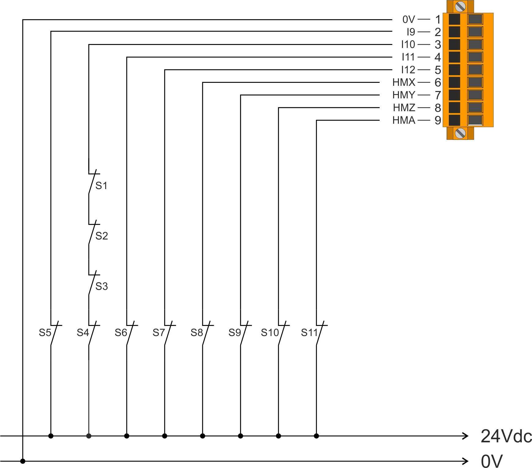
| S1 | X axis limit switch |
| S2 | Y axis limit switch |
| S3 | Z axis limit switch |
| S4 | A axis limit switch |
| S5 | Switch for pause |
| S6 | E stop |
| S7 | Start input button |
| S8 | Home X switch |
| S9 | Home Y switch |
| S10 | Home Z switch |
| S11 | Home A switch |
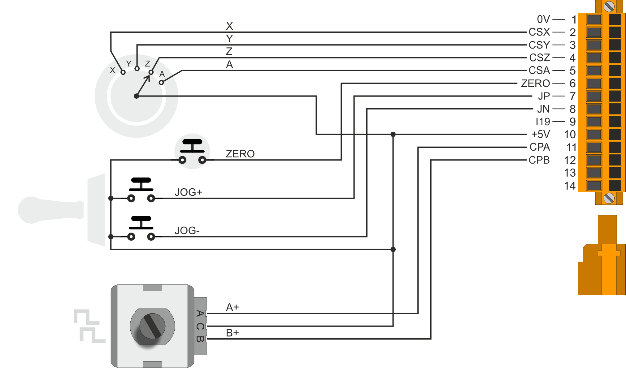
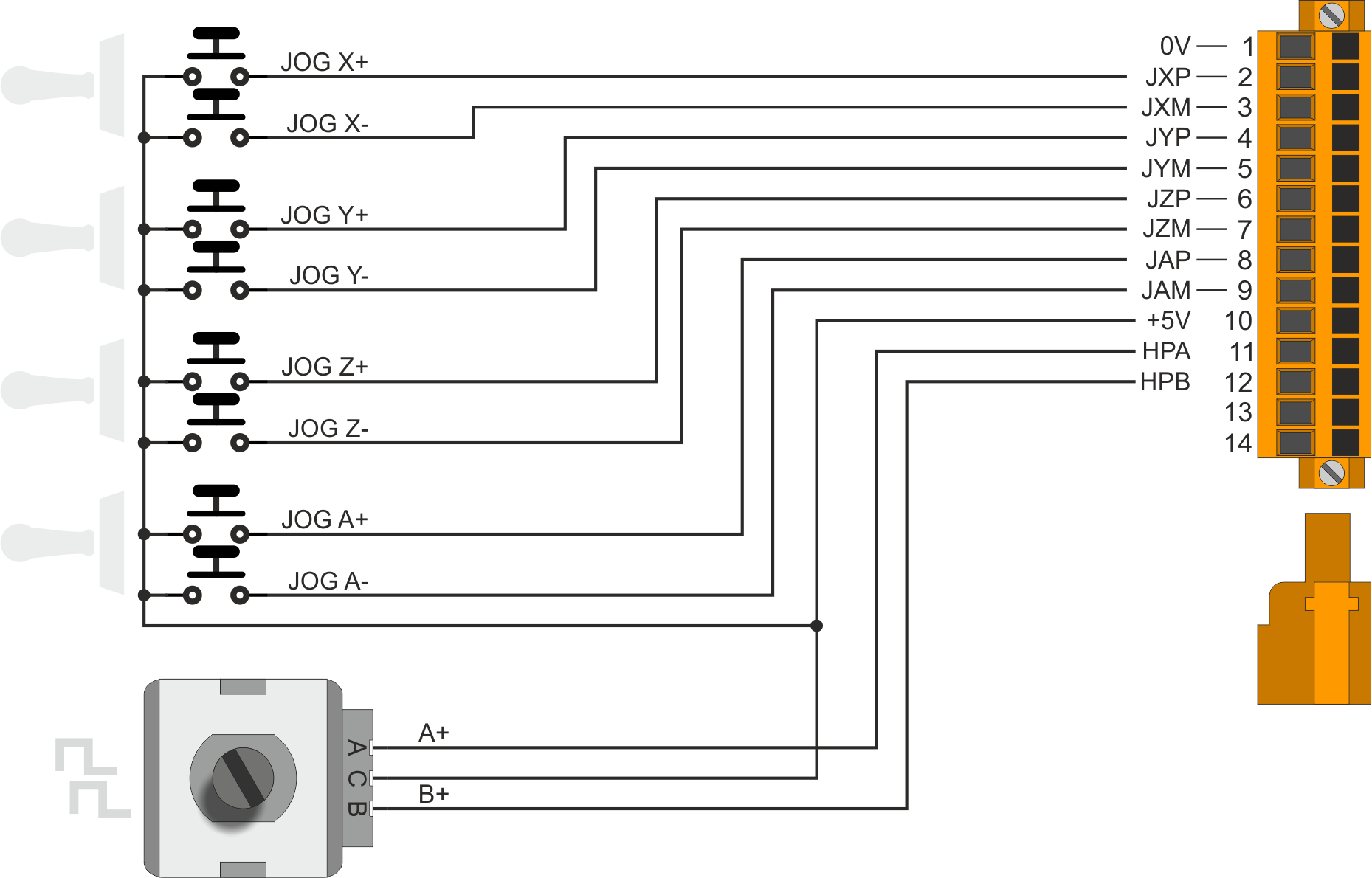
4.3.5 Handwheel or Console
The following connectors are used for different functionalities depending on the value of the “Controller type” parameter. This parameter is present in the “RosettaCNC card settings” panel → Jog.
| CN11 | Terminal | Symbol | User Input | “Jog Controller Type” parameter | ||
|---|---|---|---|---|---|---|
| HandWheel A | Single Joystick | Multiple Joystick | ||||
 | 1 | 0V | Common of digital inputs | |||
| 2 | HSX / CSX / JXP | I23 | Handwheel Sel.Axis X | Controller Sel.Axis X | Jog X+ | |
| 3 | HSY / CSY / JXM | I24 | Handwheel Sel.Axis Y | Controller Sel.Axis Y | Jog X- | |
| 4 | HSZ / CSZ / JYP | I25 | Handwheel Sel.Axis Z | Controller Sel.Axis Z | Jog Y+ | |
| 5 | HSA / CSA / JYM | I26 | Handwheel Sel.Axis A | Controller Sel.Axis A | Jog Y- | |
| 6 | HMO / ZERO / JZP | I27 | Handwheel Multiplier x1 | Zero | Jog Z+ | |
| 7 | HMT / JP / JZM | I28 | Handwheel Multiplier x10 | Jog + | Jog Z- | |
| 8 | HMH / JN / JAP | I29 | Handwheel Multiplier x100 | Jog - | Jog A+ | |
| 9 | I19 / I19 / JAM | I19 | User Input I19 | User Input I19 | User Input I19 / Jog A- | |
| 10 | +5V | 5 Volts DC output - Max power supply 50mA | ||||
| 11 | HPA / CPA / CPA | I30 | Handwheel Controller PHA - [ MPG 1 ] | Controller PHA - [ MPG 1 ] | Controller PHA - [ MPG 1 ] | |
| 12 | HPB / CPB / CPB | I31 | Handwheel Controller PHB - [ MPG 1 ] | Controller PHB - [ MPG 1 ] | Controller PHB - [ MPG 1 ] | |
| 13 | Terminals 13 and 14 internally connected to each other | |||||
| 14 | ||||||
If you are using version 1.4 or earlier of the RosettaCNC software, this connector can not be used as MPG1 and pin9 has the fixed function of ESTOP2.
4.3.5.1 Electrical features
Encoder phase terminal 11 and 12
| Type | PNP |
| Minimum acquisition time (hardware) | 1ms |
| Rated operating voltage | 5Vdc |
| Maximum voltage | 7Vdc |
| Voltage State Logic 0 | < 1.6V |
| Voltage State Logic 1 | > 2.7V |
| Absorbed current | 17mA@5V / 18mA@5V |
Inputs terminal 2÷9
| Type | PNP |
| Minimum acquisition time (hardware) | 1ms |
| Rated operating voltage | 5/12/24Vdc |
| Maximum voltage | 26Vdc |
| Voltage State Logic 0 | < 1V |
| Voltage State Logic 1 | > 3.5V |
| Absorbed current | 0.1mA@5V / 6mA@12V / 16mA@24V |
4.3.5.2 Connections examples
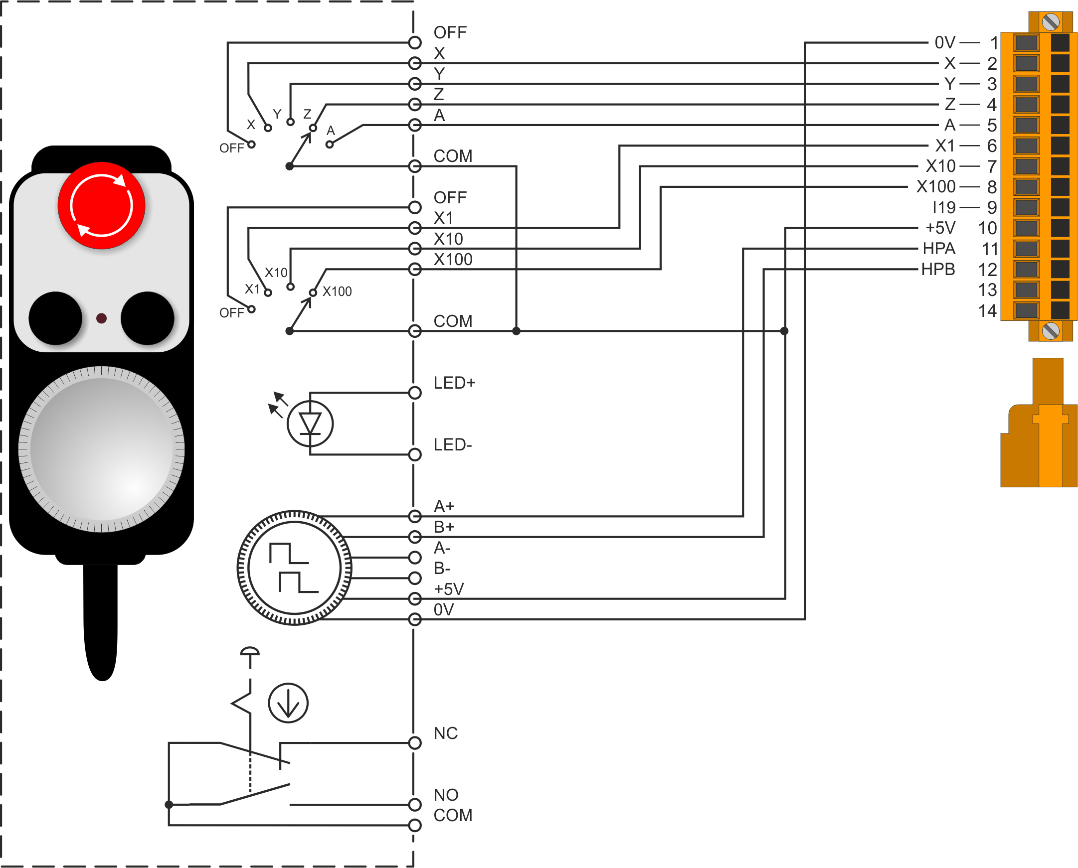
CN11 connection examples for Handwheel A
CN11 connection examples for “Single Joystick” and MPG1
CN11 connection examples for “JMultiple Joystick” ed MPG1
4.3.6 CN9
It can be used as MPG2 and as “User Inputs”. The connection of the PROBE is also permitted.
| CN9 | Terminal | User input | MPG2 | PROBE | ||||||
|---|---|---|---|---|---|---|---|---|---|---|
| Symbol | Description | Symbol | Description | Symbol | Description | |||||
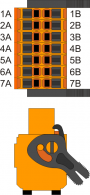 | 1A | 24Vdc | +24Vdc Output | 24Vdc | +24Vdc Output | 24Vdc | +24Vdc Output | |||
| 2A | I17 | User input I17 | PHA | Phase A | ||||||
| 3A | I18 | User input I18 | PHB | Phase B | ||||||
| 4A | I32 | User input I32 | PROBE | PROBE Sensor | ||||||
| 5A | Connected with 5B | Connected with 5B | ||||||||
| 6A | Connected with 6B | Connected with 6B | ||||||||
| 7A | Connected with 7B | |||||||||
| 1B | ||||||||||
| 2B | ||||||||||
| 3B | ||||||||||
| 4B | ||||||||||
| 5B | Connected with 5A | Connected with 5A | ||||||||
| 6B | Connected with 6A | Connected with 6A | ||||||||
| 7B | Connected with 7A | |||||||||
If you are using version 1.4 or earlier of the RosettaCNC software, the CN9 connector can only be used for PROBE input and MPG function for feed override.
4.3.6.1 Esempi di collegamento
Ingressi utente a 12-24Vdc su CN9

MPG2 on CN9

PROBE on CN9

4.3.7 CN10
It can be used as MPG3 and as “User Inputs”. The connection of the TACHO is also permitted.
| CN10 | Terminal | User input | MPG3 | TACHO | ||||||
|---|---|---|---|---|---|---|---|---|---|---|
| Symbol | Description | Symbol | Description | Symbol | Description | |||||
| | 1A | 24Vdc | +24Vdc Output | 24Vdc | +24Vdc Output | 24Vdc | +24Vdc Output | |||
| 2A | I20 | User input I20 | PHA | Phase A | ||||||
| 3A | I21 | User input I21 | PHB | Phase B | ||||||
| 4A | I22 | User input I22 | TACHO | TACHO Sensor | ||||||
| 5A | Connected with 5B | Connected with 5B | ||||||||
| 6A | Connected with 6B | Connected with 6B | ||||||||
| 7A | Connected with 7B | |||||||||
| 1B | ||||||||||
| 2B | ||||||||||
| 3B | ||||||||||
| 4B | ||||||||||
| 5B | Connected with 5A | Connected with 5A | ||||||||
| 6B | Connected with 6A | Connected with 6A | ||||||||
| 7B | Connected with 7A | |||||||||
CN10 connector available only with field I/O Expansion = 1 or 3, in order code.
4.3.7.1 Connection examples
12-24Vdc User inputs on CN10

MPG3 on CN10

TACHO 12-24V dc Input on CN10

4.4 Analog inputs
Each analogue input can be configured via the RosettaCNC software to manage an override. The settings are found in the “RosettaCNC tab Settings ” Panel → “Overrides”.
The following parameters can be set:
- Jog Speed
- Fast (G0) Speed
- Feed (G1,G2,ecc) Speed
- Spindle Speed
Furthermore, only the AN1 analog input can be used to connect a Laser type digitizer. The settings are present in the panel “RosettaCNC tab settings” → “Digitizer”.
4.4.1 CN14
| CN14 | Terminal | Symbol | Description |
|---|---|---|---|
 | 1 | VREF | Reference Voltage 1) |
| 2 | AI1 | Analog input 1 | |
| 3 | AI2 | Analog input 2 | |
| 4 | AI3 | Analog input 3 | |
| 5 | GAI | Common of Analogue Inputs |
CN14 connector and SW3 dip-switches are available only with field I/O Expansion = 2 or 3, in order code.
4.4.2 Analog Inputs settings
| SW3 | Num. Dip | Analog input 1 | Analog input 2 | Analog input 3 | ||||||
|---|---|---|---|---|---|---|---|---|---|---|
| Pot. | 0-10V | 0-20mA | Pot. | 0-10V | 0-20mA | Pot. | 0-10V | 0-20mA | ||
 | 1 | OFF | OFF | ON | X | X | X | X | X | X |
| 2 | OFF | ON | OFF | X | X | X | X | X | X | |
| 3 | X | X | X | OFF | OFF | ON | X | X | X | |
| 4 | X | X | X | OFF | ON | OFF | X | X | X | |
| 5 | X | X | X | X | X | X | OFF | OFF | ON | |
| 6 | X | X | X | X | X | X | OFF | ON | OFF | |
X = Irrelevant setting
Pot. = Potentiometer input type
0-10V = Voltmetric type input
0-20mA = Amperometric type input
4.4.3 Electrical features
4.4.3.1 Analog Input with Amperometric configuration 0-20mA
| Connection type | Amperometric (0-20 mA) |
| Resolution | 12bit |
| Input resistance | 125Ω |
| Value of damage | 25 mA |
| Max. Linearity error | + 0,1% Vfs |
| Max. Offset error | + 0,1% Vfs |
| S.n. | 71 dB |
| Conversion time | It depends on the configuration of the analog input. See section Conversion times if present 1) |
| Isolation | 1000 Vrms |

4.4.3.2 Analog input in potentiometric configuration
| Connection type | Potentiometric 1KΩ÷20KΩ |
| Resolution | 12bit |
| Reference voltage output | 2,5Vdc |
| Max output current from reference | 10mA |
| Input resistance | 10MΩ |
| Max. Linearity error | + 0,1% Vfs |
| Max. Offset error | + 0,1% Vfs |
| S.n. | 71 dB |
| Conversion time | It depends on the configuration of the analog input. See section Conversion times if present 1) |
| Isolation | 1000 Vrms |

4.4.3.3 Analog input in voltmetric configuration
| Connection type | Voltmetrico 0÷10V |
| Resolution | 12bit |
| Input resistance (Rin) | 40KΩ |
| Value of damage | 20V |
| Max. Linearity error | + 0,1% Vfs |
| Max. Offset error | + 0,1% Vfs |
| S.n. | 71 dB |
| Conversion time | It depends on the configuration of the analog input. See section Conversion times if present 1) |
| Isolation | 1000 Vrms |

4.4.4 Connection example
4.4.4.1 Generic analog inputs on CN14
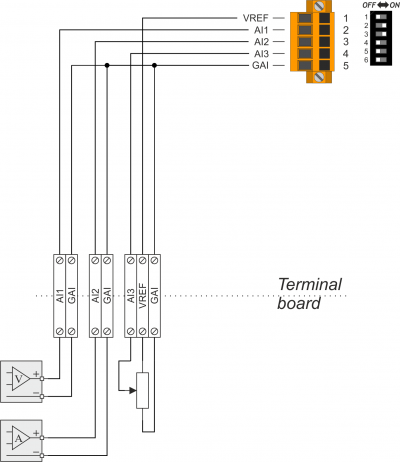
- AI1 voltmetric
- AI2 amperometric
- AI3 potenziometric
4.4.4.2 Connection of HG-C1100-P laser scanning probe on CN14
If the analog inputs expansion is present, it is possible to connect a Panasonic HG-C1100-P Micro Laser Distance Sensor to the AI1 input.
The following operations are possible through the laser sensor:
- Surface scan for 3D model (model STL file creation and TXT file with acquired data cloud).
- Scan for surface flatness mapping (creation of surface STL files and TXT files with acquired data cloud).
To function properly the sensor must be reset to the factory settings and analogue input AI1 must be set in 0-20mA amperometric configuration.
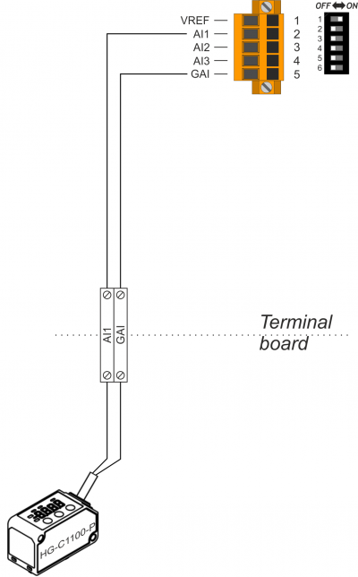
More details on the connections and configuration of the Laser sensor refer on the application note: AN003 - Panasonic HG-C Series Laser Sensor
4.5 Digital outputs
The digital outputs called “User Output” can be configured by the RosettaCNC software to perform some functions. For example: spindle ignition with rot. hourly, ignition spindle with rot. counter-clockwise, air activation, water activation, aux outputs 1..4, etc.
4.5.1 Protected outputs
4.5.1.1 Connectors
| CN7 | Terminal | Symbol | Description |
|---|---|---|---|
 | 1 | V+ | Input for power supply outputs (12÷28V dc) |
| 2 | UO1 | User output 1 | |
| 3 | UO2 | User output 2 | |
| 4 | UO3 | User output 3 | |
| 5 | UO4 | User output 4 | |
| 6 | UO5 | User output 5 | |
| 7 | UO6 | User output 6 | |
| 8 | UO7 | User output 7 | |
| 9 | UO8 | User output 8 | |
| 10 | V- | Input for power supply outputs (0V dc) |
| CN4 | Terminal | Symbol | Description |
|---|---|---|---|
| | 1 | V+ | Input for power supply outputs (12÷28V dc) |
| 2 | O9 | User output 9 | |
| 3 | O10 | User output 10 | |
| 4 | O11 | User output 11 | |
| 5 | O12 | User output 12 | |
| 6 | O13 | User output 13 | |
| 7 | O14 | User output 14 | |
| 8 | O15 | User output 15 | |
| 9 | O16 | User output 16 | |
| 10 | V- | Input for power supply outputs (0V dc) |
CN4 connector available only with field I/O Expansion = 1 or 3, in order code.
4.5.1.2 Electrical features
| Type | PNP |
| Maximum operating voltage | 28V |
| Maximum internal voltage drop | 600mV |
| Maximum current | 500mA |
| Maximum switching time from ON to OFF | 270µs |
| Maximum switching time from OFF to ON | 250µs |

4.5.1.3 CN7 connection examples

4.5.2 STEP-DIRECTION outputs
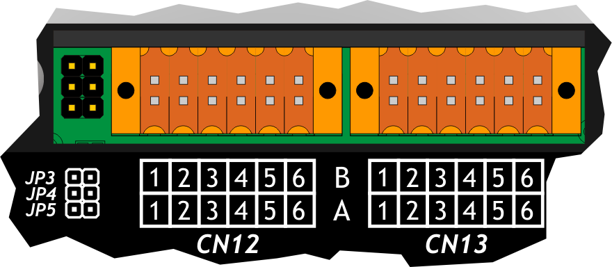
4.5.2.1 CN12
| Description | Symbol | Terminal | CN12 | Terminal | Symbol | Description | ||
|---|---|---|---|---|---|---|---|---|
| External STEP/DIR Power outputs | VDx | 1A |  | 1B | VDx | External STEP/DIR Power outputs | ||
| PNP / Line Driver | X DIRECTION Output | DIR1+ | 2A | 2B | DIR1- | X Complementary DIRECTION Output | Complementary Outputs for use in drives with Line Driver inputs | |
| X STEP Output | STEP1+ | 3A | 3B | STEP1- | X Complementary STEP Output | |||
| Y DIRECTION Output | DIR2+ | 4A | 4B | DIR2- | Y Complementary DIRECTION Output | |||
| Y STEP Output | STEP2+ | 5A | 5B | STEP2- | Y Complementary STEP Output | |||
| Common of Stepper outputs | 0V | 6A | 6B | 0V | Common of Stepper outputs | |||
4.5.2.2 CN13
| Description | Symbol | Terminal | CN13 | Terminal | Symbol | Description | ||
|---|---|---|---|---|---|---|---|---|
| External STEP/DIR Power outputs | VDx | 1A | | 1B | VDx | External STEP/DIR Power outputs | ||
| PNP / Line Driver | Z DIRECTION Output | DIR3+ | 2A | 2B | DIR3- | Z Complementary DIRECTION Output | Complementary Outputs for use in drives with Line Driver inputs | |
| Z STEP Output | STEP3+ | 3A | 3B | STEP3- | Z Complementary STEP Output | |||
| A DIRECTION Output | DIR4+ | 4A | 4B | DIR4- | A Complementary DIRECTION Output | |||
| A STEP Output | STEP4+ | 5A | 5B | STEP4- | A Complementary STEP Output | |||
| Common of Stepper outputs | 0V | 6A | 6B | 0V | Common of Stepper outputs | |||
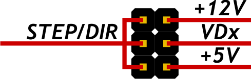
4.5.2.3 STEP-DIRECTION Output voltage Setting
Inserting one of the JP3, JP4 o JP5 jumpers, You can choose the operating voltage of the STEP and DIR outputs.
Only one jumper must be inserted at a time
If one of the two voltages is selected, 5V(JP5) or 12V(JP3), both the 1A and 1B terminals must remain disconnected.
| Name Jumper | Setting | Nominal voltage | |
|---|---|---|---|
 | JP3 | INSERTED | Selects the STEP/DIR signal voltage to 12V |
| JP4 | INSERTED | The STEP/DIR signals have a voltage equal to the value in the 1A or 1B terminals. These terminals must be supplied with an external power supply. |
|
| JP5 | INSERTED | Selects the STEP/DIR signal voltage to 5V |
.
 | JP3 |
| JP4 | |
| JP5 |
4.5.2.4 Electrical features
| Polarization type | PNP / Line-Driver |
| Maximum output frequency | up to 2MHz (depends on the order code) |
| Insulated | 1000Vpp |
| Maximum operating current | 20mA |
| Maximum VDX voltage | 27Vdc |
If stepper motor drivers are used, for a satisfactory user experience that minimizes vibrations and resonances, it is recommended to set at least 32 or 64 microsteps. However, the appropriate value must always be chosen considering the maximum frequency set and the characteristics of the driver.
Step signal during the change of direction:

The 25 microsecond time can be configured in the RosettaCNC software.
Internal diagram of Stepper motor control outputs:

4.5.2.5 Connection examples
X an Y axes PNP to 12Vdc on CN12

The voltage level of the outputs is selected by the JP3 jumpers
X and Y axes PNP to 24Vdc on CN12

The voltage level of the outputs is selected by the JP4 jumper, by selecting jumper JP4, the voltage level is equal to the voltage supplied to terminals 1A or 1B.
A and Z axes Line-Driver to 5Vdc on CN13

The voltage level of the outputs is selected via the JP5 jumpers
A and Z axes Line-Driver to 24Vdc on CN13

The voltage level of the outputs is selected via the JP4 jumpers
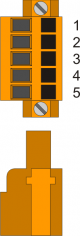
4.6 Analog outputs
4.6.1 Connector
| CN3 | Terminal | Symbol | Description |
|---|---|---|---|
 | 1 | GAO | Common of analog outputs |
| 2 | AO1 | Spindle speed | |
| 3 | AO2 | Not used | |
| 4 | GAO | Common of analog outputs |
4.6.2 Electrical features
| Connection type | In a common mode |
| Insulated | 1000Vrms |
| Voltage range (minimum empty) | 0÷10V |
| Maximum offset variation depending on temperature | +/- 5mV |
| Resolution | 16bit |
| Maximum current | 1mA |
| Variation of output depending on load | 100 µV/mA |
| Output resistance | 249Ω |

4.6.3 Connection examples on CN3

5. Connection and configuration examples
Below we will illustrate some useful wiring diagrams as an example for the design of the complete control system (electric panel).
5.1 Connecting of an XYZ pantograph
In the following example we see a wiring diagram of three stepper drives. The HOME switches are also used as a limit for the direction of movement where the homing procedure is executed. For the other direction, uses three NC switches in series and connected with the LIM input.

In this case the correct setting of the inputs in the configuration panel will be:

5.2 Configuring the Spindle command
The following outputs are available for the spindle control:
- Digital output for clockwise rotation control
- Digital output for counterclockwise rotation control
- Analog output for Speed variation
The choice of the digital outputs to use for these functions is performed in the “Outputs” panel in “RosettaCNC card settings” As shown in the picture:

The M3 or M4 codes will activate the outputs, M5 will disable them.
If RosettaCNC Board controls also the spindle rotation speed then you must connect the analog output 0÷10V to the analog input of the drive.
In the maximum speed parameter, you must set the the speed reached by the drive to the maximum voltage of 10V.
The “Start Time” parameter if set delays the execution of the Gcode to allow the spindle to reach the set speed. This time is also used when turning off the spindle.
In RosettaCNC Board are available also two digital inputs that can be used to inform the Controller when the spindle has reached the set speed or when it's stopped.
The following picture shows where to set the reference speed to 10V, The start time and the configuration of the inputs:


If the inputs are configured then the value in the start time parameter always indicates the minimum wait time although the logic level of the input does not require a wait.
5.3 Control console connection
There are several ways to design the control console. The following shows four examples:
- The easiest way is to always operate in the personal computer where the RosettaCNC software is installed. Here the Jogs, homing sequences, start and stop of Gcode programs, etc. will be controlled. Below is a graphical representation of the solution:
 .
.
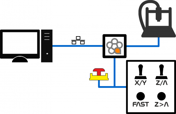
On the machine side only the ESTOP emergency button will be present (and possibly the reset button). In addition, MPG devices for override control (up to two devices) can be set up. In this case the value of the “Controller type” parameter is not significant. - With the following solution, the following control devices are wired near the machine (in addition to the ESTOP emergency button): Joystick for the X-Y-Z jog. A button for selecting Jog Fast speeds. Possible button to modify the joystick control Z in A. The following is a graphical representation of the solution:
 .
.
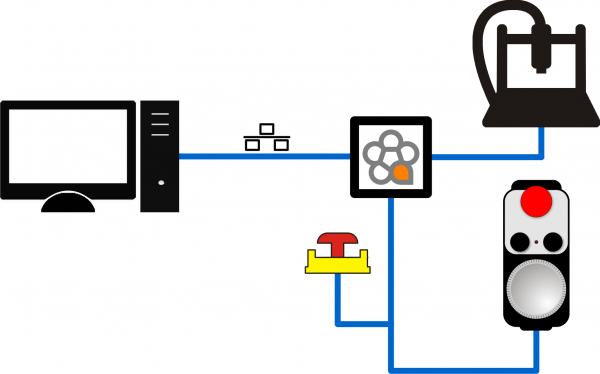
In addition an MPG device can be set up for control of override (feed, rapid, jog or spindle). In this case the value of the “Controller type” parameter must be set to “Dual Joystick”. - With the following solution a handwheel is installed near the machine to check manual movements. During operation, if set in configuration, the handwheel can also be used to control the override (configuring the operation of the MPG1 device). Finally, always if set in configuration the handwheel button can also be used to perform a reset of the selected axis. The following is a graphical representation of the solution:
 .
.
In addition to the flyer, an MPG device for override control can be set up near the machine (feed , rapid, jog or spindle). In this case, the value of the “Controller type” parameter must be set to “HandWheel A”. - With the following solution, the following control devices are wired near the machine (in addition to the ESTOP emergency button): a Joystick for the jog + and Jog-. Up to 4 buttons for axis selection. A button to reset the axis. The following is a graphical representation of the solution:
 .
.
In addition, an MPG device can be set up to control the override (feed, rapid, jog or spindle) . In this case the value of the “Controller type” parameter must be set to “Single Joystick”.


6. Diagnostic
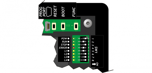
- Green Led POW, indicates that the device is powered.
- Green Led RUN, indicates that the device is working.
- Yellow Led STOP, indicates that the device is in a stop state.
- If flashes the Red Led ERROR, the controller is in an error state. You can try turning off and on again, if the problem persists, the product should be sent to technical support through the purchase channel used.
7. Virtul Inputs Outputs
The firmware implements a series of virtual user inputs and outputs that can be used with Modbus ® communication.
Below is the list of virtual user inputs and their relationship with the numbering of virtual inputs in Modbus ®.
| User input number | Virtual input number |
|---|---|
| 33 | 01 |
| 34 | 02 |
| 35 | 03 |
| 36 | 04 |
| 37 | 05 |
| 38 | 06 |
| 39 | 07 |
| 40 | 08 |
| 41 | 09 |
| 42 | 10 |
| 43 | 11 |
| 44 | 12 |
| 45 | 13 |
| 46 | 14 |
| 47 | 15 |
| 48 | 16 |
Below is the list of virtual user outputs and their relationship with the virtual output numbering in Modbus ®.
| User outputs number | Virtual outputs number |
|---|---|
| 17 | 01 |
| 18 | 02 |
| 19 | 03 |
| 20 | 04 |
| 21 | 05 |
| 22 | 06 |
| 23 | 07 |
| 24 | 08 |
8. Index Inputs
Starting from 1.52 firmware version it is possible to use these user inputs as index during homing.
| User Inputs number | Connector |
|---|---|
| 32 | CN9 |
| 22 | CN10 |
9. Accessory IQ023
Starting from software version 1.9.4 it is possible to connect the IQ023 accessory to the control PC.
The use of this accessory must be enabled in the board settings.
The resources of the accessory are mapped as follows:
| IQ023 resource | RosettaCNC board resource |
|---|---|
| D01 | User input 49 |
| D02 | User input 50 |
| D03 | User input 51 |
| D04 | User input 52 |
| D05 | User input 53 |
| D06 | User input 54 |
| D07 | User input 55 |
| D08 | User input 56 |
| D09 | User input 57 |
| D10 | User input 58 |
| D11 | User input 59 |
| D12 | User input 60 |
| D13 | User input 61 |
| D14 | User input 62 |
| D15 | User input 63 |
| D16 | User input 64 |
| D17 | User input 65 |
| D18 | User input 66 |
| D19 | User input 67 |
| D20 | User input 68 |
| D21 | User input 69 |
| D22 | User input 70 |
| D23 | User input 71 |
| D24 | User input 72 |
| E1A Phase A MPG 1 | User input 73 |
| E1B Phase B MPG 1 | User input 74 |
| E2A Phase A MPG 2 | User input 75 |
| E2B Phase B MPG 2 | User input 76 |
| E3A Phase A MPG 3 | User input 77 |
| E3B Phase B MPG 3 | User input 78 |
| E4A Phase A MPG 4 | User input 79 |
| E4B Phase B MPG 4 | User input 80 |
| A0 | Analog input 04 |
| A1 | Analog input 05 |
| A2 | Analog input 06 |
| A3 | Analog input 07 |
| A4 | Analog input 08 |
| A5 | Analog input 09 |
| A6 | Analog input 10 |
| A7 | Analog input 11 |
| MPG 1 | MPG 5 |
| MPG 2 | MPG 6 |
| MPG 3 | MPG 7 |
| MPG 4 | MPG 8 |
10. Previous hardware versions
Below are links to consult the previous hardware versions of the product.
| Modello | Part number |
|---|---|
| Hardware version 01 | User Manual |
11. Acknowledgement
All those who want to contribute to the improvement of this documentation are in advance thanks to the reporting inaccuracies or incorrect content. Write to the address: support@rosettacnc.com