9. Virtual Machines
An important added value to Control Software is the Virtual Machine.
A Virtual Machine is a graphical representation of a real CNC machine managed by Control Software which permits to:
- Simplify the operations of Toolpath analysis with Simulator.
- Help to avoid Toolpath collisions visually evaluating any axis movement post-CAM and pre-execution of G-Code in CNC machine.
- Give to end-user a better awareness of what CNC is doing and what the CNC will do.
Follow an example of a 5-Axis Virtual Machine available after Control Software installation:
9.1 Virtual Machine Editor
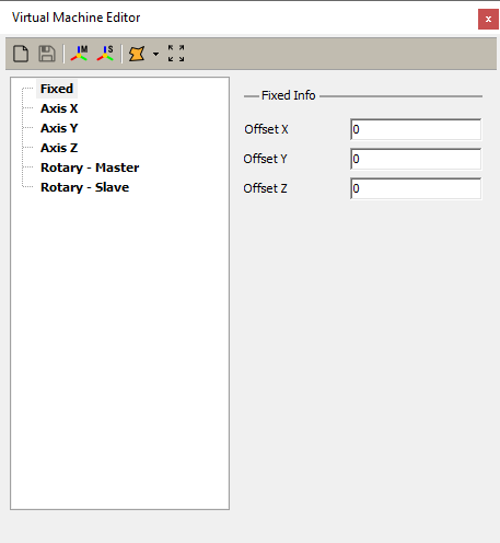
Through the Virtual Machine Editor, it is possible to edit and modify the Virtual Machine of the current machine.
To show the Virtual Machine Editor use the main menu View → Show Virtual Machine Editor:
A Virtual Machine is composed of the following elements:
- Part
- A Part represents a physical part of machine Kinematics:
- Fixed
- The fixed branch will collect all fixed Geometries, AKA elements, of CNC as basement, structure, doors, barriers, etc.
- Axis X..Z
- The Axis X to Axis Z will collect all Geometries related to an axis as the spindle, bridge, etc.
- Master
- The Master will collect all Geometries related to the Master axis and dependent by Kinematics chosen.
- Slave
- The Slave will collect all Geometries related to the Slave axis and dependent by Kinematics chosen.
- Geometry
- A Geometry represents a 3D graphical element of a Part in the form of an STL (“STereoLithography”) file.
To simplify the Virtual Machine creation we have used a fixed structure of parts that can represent any Kinematics.
The Virtual Machine automatically adapts its graphical representation depending on CNC Board Kinematics Model parameter, without the need to change the structure of its parts.
For example, in the case of a Trivial Kinematics, the parts Master and Slave should be left empty because are useless for it following this rules:
| Kinematics Model | Part Meaning |
|---|---|
TrivialIndependent Rotational Axes |
|
Rotary Table A/C |
|
Rotary Table B/C |
|
Tilting Spindle A/C |
|
Part types have custom properties that permit them to tailor the Virtual Machine behavior and interaction with the machine kinematics.
Follow the description of properties for each Part type.
9.1.1 Fixed Info
- Offset X/Y/Z
- Defines the main offsets X/Y/Z applied to all Geometries of the Fixed branch moving them in tridimensional space.
- If the CAD project is available all Geometries positions can be changed before to export STL files.
- When an STL is exported it maintains the origin offsets of owner component which can be also different by project origin.
- In case that only STL files are available and they are wrong placed in space, these fields permit to fix it.
- A typical case of wrong positions is that often STL 0/0/0 is the same as CAD component origin but not aligned to machine MCS zero.
- In the following sample the CNC customer sent us only STL files with a wrong MCS zero far from cutting head and then fixed with Part Offsets:
- IMPORTANT RULE
- An important rule to follow, to do fastly and simply a Virtual Machine, is to have all STLs below a unique origin and place this origin as machine MCS zero.
- To get this read carefully the chapter “Virtual Machine from CAD”.
9.2 Virtual Machine from CAD
9.3 Virtual Machine Files
Each CNC machine can have a virtual machine that represents it physically.
In the machine folder, where are also available customize, macros, media, etc folders there is the vm folder.
All files required by a Virtual machine are in the VM folder.
The vm folder of current machine, eg: Quaser-MF630 of installation package, is reachable at:
%appdata%\RosettaCNC-1\machines\Quaser-MF630\vm:
A Virtual Machine is composed of a machine description file (VM.XML) plus an arbitrary number of mesh files (.STL) which define 3D parts of it.
The VM.XML file will contain the machine description and is in encrypted form.
The .STL files could be either in ASCII or BINARY format, but BINARY is the right choice for performances and compatibility.


