This is an old revision of the document!
4. Program Settings
Program Settings panel permits to sets the Control Software behavior.
The following images represent the settings captured from the default machine just as after a clean installation and are only for samples.
4.1 General
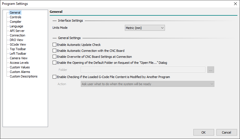
4.1.0.1 Interface Settings
- Units Mode
- Permits to define the Units Mode used in the Control Software UI between
Metric (mm)andImperial (in). - It ONLY sets the measures representation in the UI so, in the G-Code, the Units Mode can be defined with a
G20orG21and can be different than UI. - During the G-Code Program/Macro/MDI execution,
G20andG21commands can be freely mixed but UI representation will be fixed to this setting. - All fields and settings of the UI are affected by the Units Mode except for Board Settings which are always expressed in the Metric System.
4.1.0.2 General Settings
- Enable Automatic Update Check
- If enabled actives automatic check, at Control Software start and every 3 minutes, of online updates.
- If an update is available a blinking advice message will be shown in Control Software Status Bar.
- If disabled you can manually check if an update is available with the main menu
Help → Check for Updates. - Update Manager checks for online updates regarding only the current version, eg: 1.9.x search only for 1.9 branches.
- The update Check feature can be locked, to the end-user, using Access Levels settings.
- PS: During the Update phase, if Windows UWF Status is found Enabled, the update procedure will be stopped because is not possible to update permanently files in a UWF protected disk.
- Enable Automatic Connection with the CNC Board
- If enabled it actives automatic connection with CNC Board at Control Software starts.
- Enable Overwrite of CNC Board Settings at Connection
- When Control Software opens a connection with CNC Board it checks if Board Settings in CNC Board are the same as Board Settings stored on Control Software.
- If settings are different, and this option is enabled, the Control Software automatically sent Board settings on Control Software to CNC Board.
- If this option is disabled, a prompt user dialog will show the state and will ask the end-user to Download Control Software Board Settings to CNC Board or Upload CNC Board settings to Control Software.
- This feature is very useful when the same CNC Board is used in a CNC machine that uses more than one configuration, such as a 3-Axis vertical spindle or a 4-Axis horizontal spindle.
- Enable the Opening of the Default Folder on Request of the “Open File…” Dialog
- If enabled it permits to define the default folder open on Request of the main menu
File → Open File…dialog or pressing theF12key. - Special Windows folder shortcuts can be used here (for eg.
%APPDATA%, to reach the user application data folder).
- Enable Checking if the Loaded G-Code File Content is Modified by Another Program
- If enabled it permits to define how to update the loaded G-Code file when a new version is available.
- This happens, for eg., when a user asks CAM to create a new G-Code output file or when the G-Code file is modified by the user with a text editor.
- Four different actions could be chosen:
- Ask user what to do if the system is ready
- When the loaded G-Code program changes externally, and the CNC is in IDLE, a prompt dialog asks the user what to do.
- Ask user what to do when the system will be ready
- When the loaded G-Code program changes externally, and the CNC is not in IDLE the check system waits for CNC IDLE, then a prompt dialog asks the user what to do.
- Load automatically newer file content if the system is ready
- When the loaded G-Code program changes externally, and the CNC is in IDLE, the G-Code program will be automatically reloaded.
- Load automatically newer file content when the system will be ready
- When the loaded G-Code program changes externally, and the CNC is not in IDLE the check system waits for CNC IDLE, then the G-Code program will be automatically reloaded.
4.2 Controls
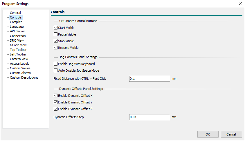
4.2.0.1 CNC Board Control Buttons
- Start Visible
- Defines if the Start button will be visible, or not, in the CNC Board Control Bar.
- Pause Visible
- Defines if the Pause button will be visible, or not, in the CNC Board Control Bar.
- Stop Visible
- Defines if the Stop button will be visible, or not, in the CNC Board Control Bar.
- Resume Visible
- Defines if the Resume button will be visible, or not, in the CNC Board Control Bar.
4.2.0.2 Jog Controls Panel Settings
- Enable Jog With Keyboard
- Enables the Jog control with the keyboard.
- With the Keyboard is possible to control X-Axis (
Left/Rightkeys), Y-Axis (Up/Downkeys), and Z-Axis (Page Up/Page Downkeys). - To do Jog with the keyboard the Jog Controls panel axis control must be visible and focused.
- To focus it click the mouse in the near zone or press the
F1key one or two times till the blue focus rectangle is shown.
- Auto Disable Jog Space Mode
- Enables the auto-disable of Jog Space Mode.
- When Jog movements are made with the Jog Controls panel and the
Jog Spacefield is checked, withAuto Disable Jog Space Modeactive, at end of the movement theJog Spacefield will be automatically disabled.
- Fixed Distance with CTRL + Fast Click
- Defines the fixed distance used when with the
CTLRkey pressed a fast key/left-mouse click is done in the desired axis movement. - When the
CTRLkey is pressed a fast click, below 500 ms of duration, moves the selected axis of programmed distance. - When the
CTRLkey is pressed a long long click, over 500 ms of duration, executes a normal Jog axis movement but with an initial delay of 500 ms required to detect if in the fixed distance mode.
4.2.0.3 Dynamic Offsets Panel Settings
Dynamic Offsets permit to add positive/negative offset to X/Y/Z-Axis during CNC working using the related floating panel.
A change of Dynamic Offsets is possible only with CNC in RUN State and in a range of +3/-3mm.
Don't use Dynamic Offsets during RTCP enabled movements (G43.4 or G43.7).
- Enable Dynamic Offset X
- Enables the Dynamic Offset feature for X-Axis.
- Enable Dynamic Offset Y
- Enables the Dynamic Offset feature for Y-Axis.
- Enable Dynamic Offset Z
- Enables the Dynamic Offset feature for Z-Axis.
- Dynamic Offsets Step
- Defines the minimum step (+ or -) of Dynamic Offsets value change.
4.3 Compiler
4.3.1 General
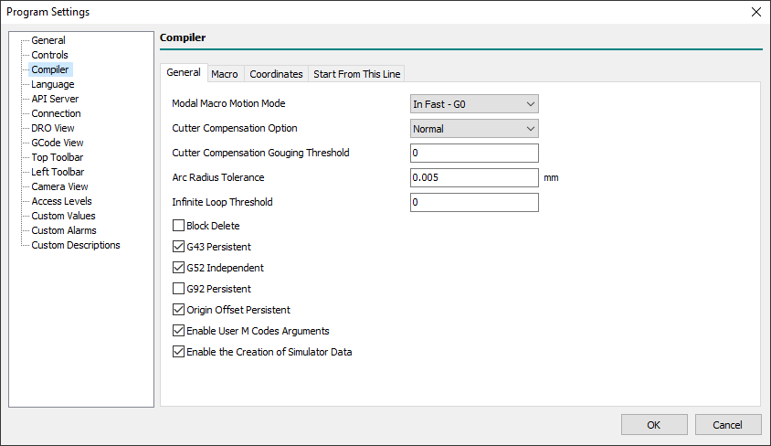
- Modal Macro Motion Mode
- Define the default motion mode used to perform the movements between two custom macro repetitions (Look at Modal Macro calls):
- In Fast - G0
- A fast movement with the
G0command will be performed.
- In Feed - G1
- A feed movement with the
G1command will be performed.
- In the G-Code Program/Macro/MDI, with the
G10 L100 P5800 V<value>command is possible to specify a different value from the default (#5800 = 0 → G0;#5800 = 1 → G1). - At the start of the G-Code Program/Macro/MDI, the default motion mode value will be always restored.
- Cutter Compensation Option
- Defines how the CNC Board will manage the Tool Cutter Compensation enabled with
G41/G41.1andG42/G42.1commands. - The available options are:
- NIST
- The default NIST mode.
- Easy Lead-In
- Delays the first movement of the entry move until the following line or arc is specified.
- When the second entry motion is specified it performs the entry move to a position tangent to the beginning of the second line or arc.
- This option works well with some CADs such as Fusion360 indeed no gouging errors are generated.
- Normal
- It is the only option that can handle concave corners and concave arcs.
- PS: For more info look at Tool Compensation Entry Options.
- Cutter Compensation Gouging Threshold
- Defines the cutter compensation gouging threshold applied to
G41/G41.1orG42/G42.1commands whenCutter Compensation Optionis set toNormal.
- Arc Radius Tolerance
- Defines the maximum accepted difference of the distance between the start point and the center of an arc and that between the end-point and the center of the arc before generating a compilation error.
- The value should be also equal to or higher than the greatest axes quantum movement (Axis Quantum = CNC Board axis
Measure / Pulses).
- Infinite Loop Threshold
- Defines how to manage a possible infinite loop in
WHILEcommands. - When the value is set to 0 means: Continue till the
WHILEexpression is satisfied or the user press theESCkey to abort the current compilation. - When the value is set > 1 means: Continue till the
WHILEexpression is satisfied or the user press theESCkey to abort the current compilation or then-valueloops are reached.
- Esample of an infinite loop:
- In this case the coder missed to increment #1 value (eg:
#1=[#1+1]) so the loop with Infinite Loop Threshold = 0 will continue to infinite. - For example with Infinite Loop Threshold = 10000, after 10000 loops the compiler will notice an error and stop compiling automatically.
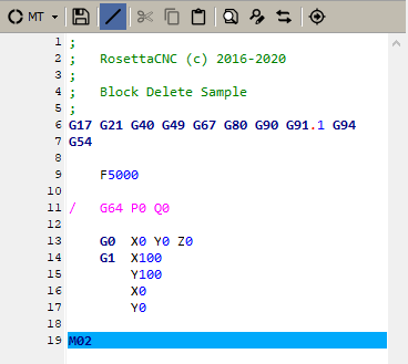
- Block Delete
- Enables Block Delete management.
- Block delete is used in a program by placing a forward slash (
/) at the beginning of the line. - It is a useful function that allows the operator to skip the blocks within the program.
- When the Block Delete option is enabled, and G-Code Editor Block Delete icon is active, all G-Code lines with
/will be disabled and not executed. - The G-Code located to the right of an enabled Block Delete is still subject to syntactic check even if the code execution will be skipped:
 |
- G43 Persistent
- Defines if
G43compensation is persistent in CNC Board at end of a G-Code Program/Macro/MDI execution.
- G52 Independent
- Defines if
G52is independent between changes of active WCS in a G-Code Program/Macro/MDI execution.
- G92 Persistent
- Defines if
G92offsets are persistent in the CNC Board at end of a G-Code Program/Macro/MDI execution.
- Origin Offset Persistent
- Defines if the changing of the selected World Coordinate System (WCS) made in the G-Code Program/Macro/MDI is kept at end of code execution:
- Checked
- At the start of the program execution, the current active WCS is used.
- At the end of the program execution, any changing of selected WCS with the
G54/G55/G56/G57/G58/G59.1/G59.2/G59.3commands will be kept. - In the case of the program stop, the current selected WCS is kept.
- Unchecked
- At the start of the program execution, the current active WCS is used.
- At the end of the program execution, any changing of selected WCS with the
G54/G55/G56/G57/G58/G59.1/G59.2/G59.3commands will be lost and WCS 1 (G54) is applied. - In the case of the program stop, the current selected WCS is kept.
The changes to any WCS origin offset values made with the G10 L2 Pp Xx Yy Zz Aa Bb Cc command are not affected by this parameter.
- Enable User M Code Arguments
- Define if the user-defined M macros will accept arguments, eg:
M201 A10 J-1.3.
- Enable the Creation of Simulator Data
- Defines if the creation of Simulator Data is enabled.
- Disabling Simulator Data will improve G-Code program compilation time and will reduce the memory used by the PC.
- In the 32-bit version of the control software, when the estimated execution time of the G-code exceeds 5 hours, the simulator data is automatically disabled.
4.3.2 Macro
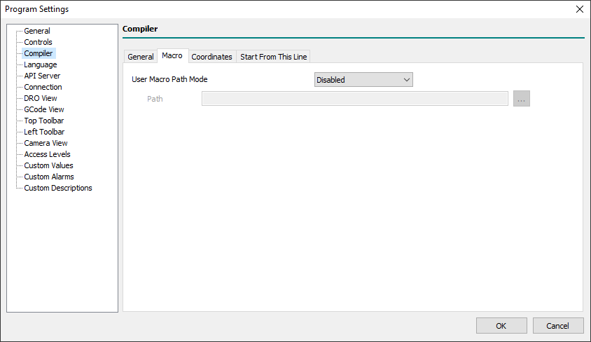
- User Macro Path Mode
- Two types of macros are available in the G-Code language: Machine Macros and User Macros.
- The Machine Macros are stored in the folder
%APPDATA%\RosettaCNC-1-\<machine>\macros. - To quickly reach the actual Machine Macros folder, you can use the “
File → Open Macro Folder” menu. - Machine Macros can be used to create new
G&Mcommands, provide well-defined CNC functions such as tool change, or subroutines that can be called up by number/name using theM98/G65/G66/CALLcommands. - User Macros can be ONLY used to create subprogram callables by name.
- User Macro Path is used ONLY if the subprogram is called with the prefix
/, eg:G65 P“/square_pocket.ngc” W100. H100. Z-40. R-5. T2. - The User Macro Path Mode allows this by choosing from the following options:
- Disabled
- The User Macro feature is disabled.
- GCode File Path
- The User Macros are searched in the same path as the currently opened G-Code Program.
- User Defined Path
- The User Macros are searched in the below-defined path.
- Path
- Defines the path where the User Macros are stored when the User Defined Path option was chosen.
4.3.3 Coordinates
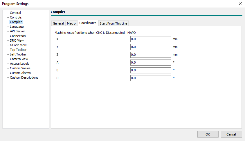
- Machine Axes Positions when CNC is Disconnected - MAPD
- Defines the machine axes positions used in Control software when not connected with a CNC Board.
- Typically these values are used how axes start points during G-Code simulation with internal software Simulator and without a CNC Board connected.
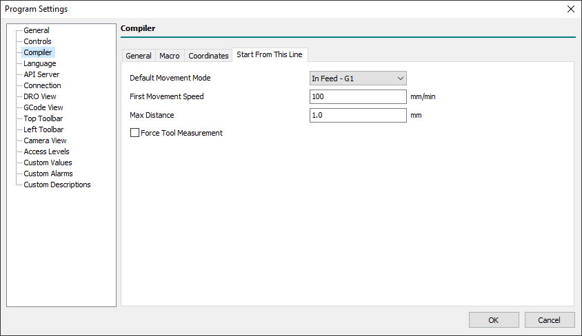
4.3.4 Start From This Line
The System Macro restart.ngc manages all the activities necessary to START machining from a specific program line or to RESUME machining stopped with a STOP command from the last executed line or from one of your choice.
However, when the macro is not available, a series of minimal operations are performed.
The following parameters allow you to configure these operations.
- Default Movement Mode
- Defines how the CNC make the default movements to start Start/Restart from a line from:
- In Feed - G1:
default movements will use theG1command (feed movement). - In Fast - G0:
default movements will use theG0command (fast movement). - Handheld by the PLC:
default movements are managed by PLC internal strategy.
- First Movement Speed
- Defines the default movement speed when Default Movement Mode is set to In Feed - G1.
- Max Distance
- Defines the maximum accepted distance between the actual CNC position and the first CNC target position described in the G code.
- If the distance is greater than Maximum Distance, an error message will be displayed in the dialog box and no movement will be made.
- Force Tool Measurement
- If enabled, if the currently loaded tool is different from the required tool, the Tool Change procedure will be forced otherwise an error message will signal the case and no movement will be performed.
PS: This is a very poor way to manage a START/RESTART from a line. The use of the restart.ngc macro is the right way to get better management of that.
4.4 Language
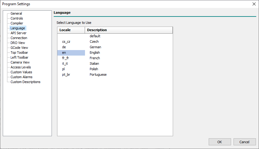
- Select Language to Use
- Permits to define the UI language to use choosing from available languages.
- Any change of current language requires a Control Software re-start to be fully applied.
PS: The Default item means “Use current computer default language, if present in the list, otherwise use the English language”.
4.5 API Server
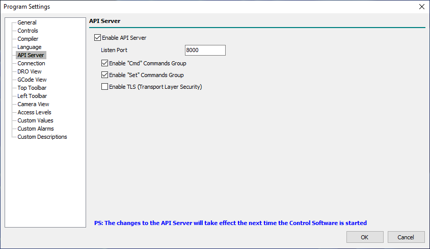
Through the API Server, the Control Software exports a part of its API which can be used with external client applications.
The API server is a TCP/IP Server listening on localhost with a communication protocol based on JSON Request/Response packets.
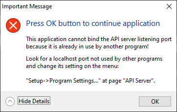
The API Server, if enabled, will be activated automatically when the Control Software is started.
If, when starting the Control Software, the API Server Listening Port is found to be already in use, the following dialog will be displayed:
- Enable API Server
- Enabled the Control Software API Server.
- Listen Port
- Localhost Listening Port of the API Server.
- It can be any localhost port not already used in the range 0 to 65535.
- Enable “Cmd” Commands Group
- Enable the API Server “Cmd” commands group.
- Enable “Set” Commands Group
- Enable the API Server “Set” commands group.
- Enable “TLS” (Transport Layer Security)
- NOT YET IMPLEMENTED!
PS: The changes to the API Server will take effect the next time the Software Control is started.
4.6 Connection
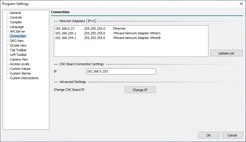
4.6.0.1 Network Adapters [IPv4]
This panel displays all the Network Adapters for the Internet Protocol version 4 that can be reached by the Control Software.
For each adapter in the list, the IP address, the NET MASK and the NET NAME are available.
- Update List
- Updates the list of Network Adapters.
- This is necessary if you change the Network configuration, eg: enabling a new LAN/WIFI connection.
4.6.0.2 CNC Board Connection Settings
- IP
- Defines the IP of the CNC Board to connect with.
4.6.0.3 Advanced Settings
- Change IP
- Permits to discovery and change the IP Settings of the CNC Boards connected in the Network.
- For more information, see the “How To: Change Board IP” page.
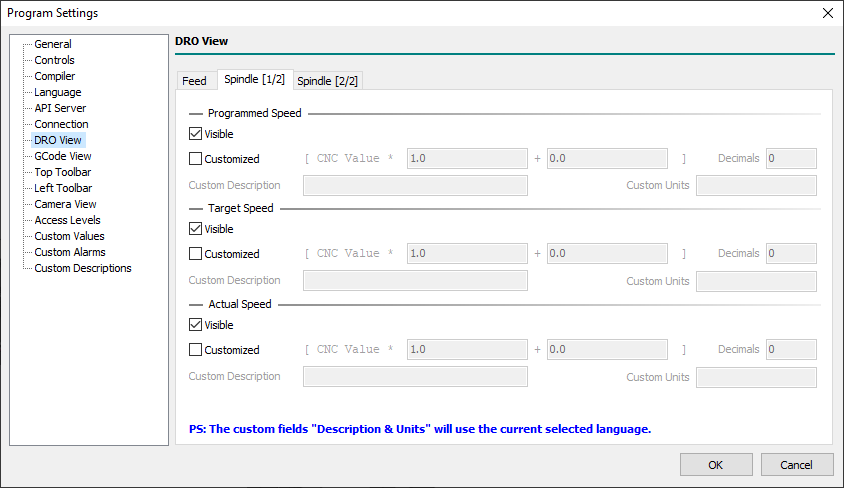
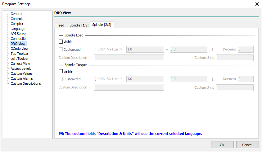
4.7 DRO View
4.7.1 Feed

4.7.2 Spindle [1/2]
4.7.3 Spindle [2/2]
4.8 GCode View
4.8.1 General
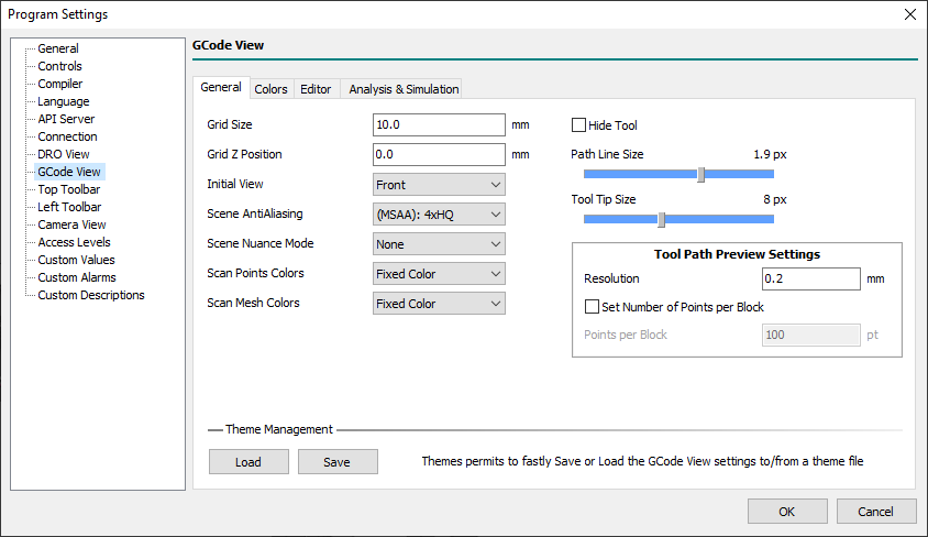
- Grid Size
- Defines the size of the Grid used to represent the XY-Axis area in the machine coordinates.
- Grid Z Position
- Defines the Z machine coordinate where the Grid will be placed.
- Is usual to place this value at the same Z-Axis Min Limit value.
- Initial View
- Defines the initial 3D view mode used as default when the Control Software is executed.
- The graphical engine will automatically fit the 3D scene objects to be all shown in the display.
- Choose one of the following values:
- Front
- The initial view will be on the front of the CNC.
- Back
- The initial view will be on the back of the CNC.
- Top
- The initial view will be at the top of the CNC.
- Bottom
- The initial view will be at the bottom of the CNC.
- Left
- The initial view will be on the left of the CNC.
- Right
- The initial view will be on the right of the CNC.
- ISO 1..9
- The initial view will be one of the ISO perspective modes.
- Custom View 1..4
- The initial view will be one of the ISO perspective custom modes.
- Scene AntiAliasing
- Defines the strength of Antialiasing filter applied by the graphical engine to 3D scene:
- Default
- Antialiasing disabled (will take the first available pixel format).
- None
- Antialiasing disabled (will take the first available pixel format).
- (MSAA): 2x
- Multisampled Antialiasing (MSAA): 2x.
- (MSAA): 2xHQ
- Multisample Antialiasing (MSAA): 2x High Quality.
- (MSAA): 4x
- Multisampled Antialiasing (MSAA): 4x.
- (MSAA): 4xHQ
- Multisampled Antialiasing (MSAA): 4x High Quality.
- (MSAA): 6x
- Multisampled Antialiasing (MSAA): 6x.
- (MSAA): 8x
- Multisampled Antialiasing (MSAA): 8x.
- (MSAA): 16x
- Multisampled Antialiasing (MSAA): 16x.
- (CSAA): 8x
- Coverage Sampled Antialiasing (CSAA): 8x.
- (CSAA): 8xHQ
- Coverage Sampled Antialiasing (CSAA): 8x High Quality.
- (CSAA): 16x
- Coverage Sampled Antialiasing (CSAA): 16x.
- (CSAA): 16xHQ
- Coverage Sampled Antialiasing (CSAA): 16x High Quality.
Default and None are similar but not the same.
Default does not touch the settings related to sample buffers of the OpenGL context from what defined in GPU Windows Settings.
None disables WGL_SAMPLE_BUFFERS_ARB and therefore the Anti-Aliasing management completely.
MSAA stays for Multi Sampled Antialiasing.
CSAA stays for Coverage Sampled Antialiasing.
Coverage Sampled Antialiasing (CSAA) is supported by NVIDIA cards (CSAA Tutorial)
- Scene Nuance Mode
- Xxx…
- Scan Points Colors
- Xxx…
- Scan Mesh Colors
- Xxx…
- Hide Tool
- Xxx…
- Path Line Size
- Xxx…
- Tool Tip Size
- Xxx…
4.8.1.1 Tool Path Preview Settings
- Resolution
- Xxx…
- Set Number of Points per Block
- Xxx…
- Points per Block
- Xxx…
4.8.1.2 Theme Management
- Load
- Permits to load a saved theme from a file.
- Save
- Permits to save the current theme in a file.
4.8.2 Colors
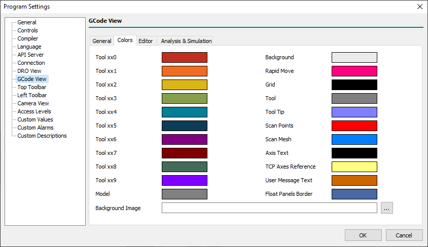
- Tool xx0..xx9
- Defines the colors assigned to Tools.
- The color assigned to the Tool depends on the last Tool digit number.
- Eg: Tool 1, 11, 21, .. share the same Tool color as 2, 22, 92, and so on.
- Model
- Defines the color of the G-Code program Model geometry.
- The G-Code program model is an STL file with the same G-Code program name, but extension STL, loaded when a G-Code program is loaded.
- Background
- Defines the 3D scene background color.
- This color is used when in the machine
customizepath is not available thebackground.pngbackground image. - If in machine
customizepath is available thebackground.pngimage the system will use the image instead of background color.
- Rapid Move
- Defines the color for toolpath G00 (rapid) movements.
- Grid
- Defines the color of the working area Grid.
- Tool
- Defines the color of the Tool Body.
- Tool Tip
- Defines the color of the Tool Tip Body.
- Scan Points
- Defines the color of Scan Points during Scanning 3D/Scanning Surface features.
- Scan Mesh
- Defines the
- Axis Text
- Defines the color of the Axis text in MCS origin.
- User Message Text
- Define the color of the User Message for the M109 command.
- Float Panels Border
- Defines the Float Panels border color for Jog/MDI/etc.
4.8.3 Editor
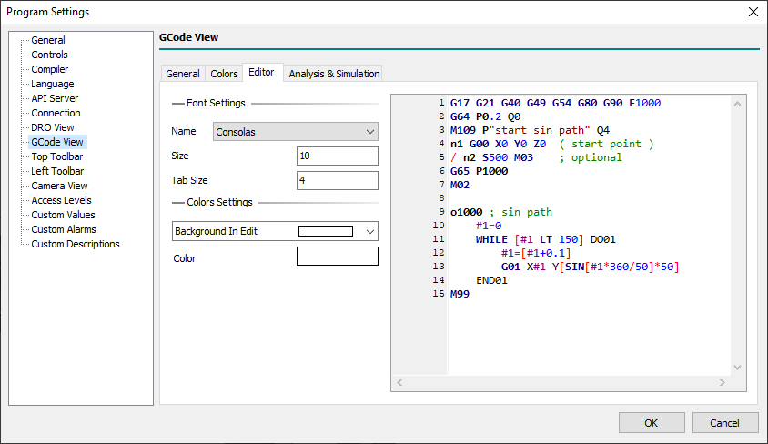
4.8.3.1 Font Settings
- Name
- Xxx…
- Size
- Xxx…
- Tab Size
- Xxx…
4.8.3.2 Color Settings Settings
- Color
- Xxx…
4.8.4 Analysis & Simulation
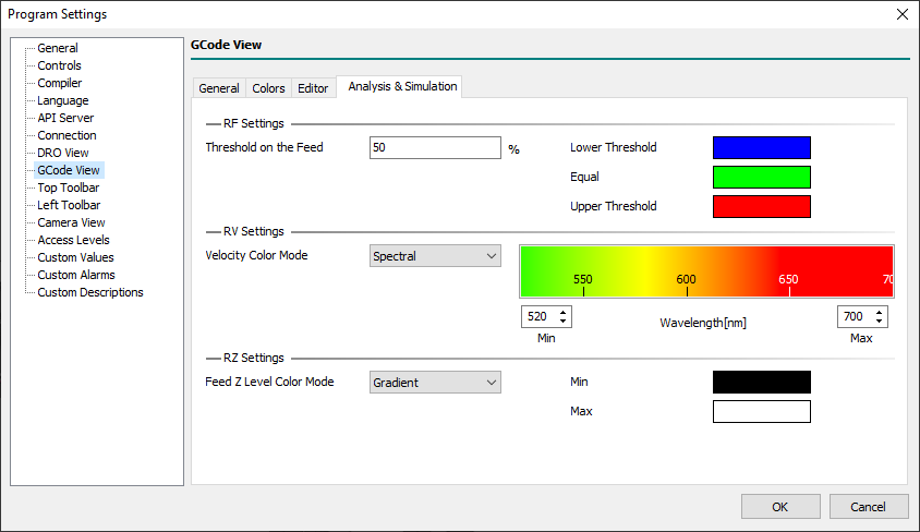
4.8.4.1 RF Settings
- Threshold on the Feed
- Xxx…
- Lower Threshold
- Xxx…
- Equal
- Xxx…
- Upper Threshold
- Xxx…
4.8.4.2 RV Settings
- Velocity Color Mode
- Xxx…
4.8.4.2.1 Spectral
- Min
- Xxx…
- Max
- Xxx…
4.8.4.2.2 Gradient
- Min
- Xxx…
- Max
- Xxx…
4.8.4.3 RZ Settings
- Feed Z Level Color Mode
- Xxx…
4.8.4.3.1 Spectral
- Min
- Xxx…
- Max
- Xxx…
4.8.4.3.2 Gradient
- Min
- Xxx…
- Max
- Xxx…
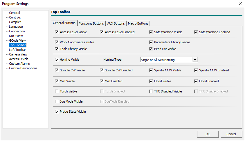
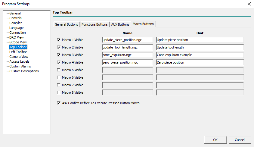
4.9 Top Toolbar View
Through this panel and related sheets, it is possible to set the visibility of buttons in the top toolbar.
4.9.1 General Buttons
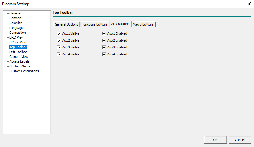
4.9.2 AUX Buttons
4.9.3 Macro Buttons
Through this sheet, it is possible to show and define the top toolbar macro button's actions.
4.10 Left Toolbar View
Through this panel, it is possible to set the visibility of some button in the left toolbar, also know as Machine Toolbar.
4.10.1 General Buttons
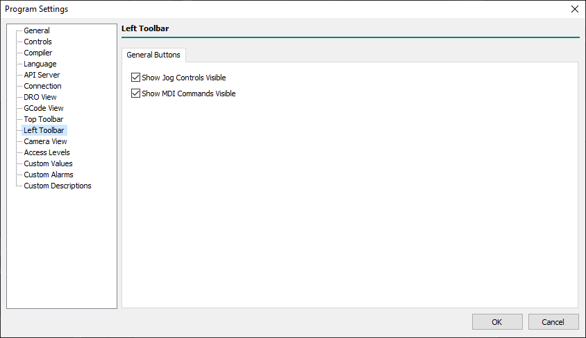
- Show Jog Controls Visible
- Defines the visibility of the left toolbar
Show Jog Controlsbutton. - When the button is not visible the
Jog Controlspanel can be yet shown/hidden pressing theF1key or using the related main menu item. - When the UI central area view is not in
Main View, showing or hiding theJog Controlspanel will automatically switch the view toMain View.
- Show MDI Commands Visible
- Defines the visibility of the left toolbar
Show MDI Commandsbutton. - When the button is not visible the
MDI Commandspanel can be yet shown/hidden pressing theF4key or using the related main menu item. - When the UI central area view is not in
Main View, showing or hiding theMDI Controlspanel will automatically switch the view toMain View.
4.11 Camera View
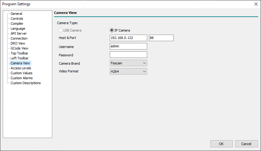
- Camera Type
- Defines the type of connected camera between “USB Camera” and “IP Camera”.
- At the moment ONLY IP cameras are supported.
- USB Camera
- Sets the Vision Engine to work with a USB Camera.
- IP Camera
- Sets the Vision Engine to work with an IP Camera.
- Host & Port
- Defines the Host & Port of the IP Camera.
- Username
- Defines the Username necessary to connect to the IP Camera internal server.
- Password
- Defines the Password necessary to connect to the IP Camera internal server.
- Camera Brand
- Defines the brand of IP Camera from one of supported brands:
- Undefined
- Foscam
- Panasonic
- Aviosys
- Smartec
- ACTi
- ArcVision
- Axis
- DLink
- Beward
- Genius
- Planet
- Samsung
- Trendnet
- Vivotek
- Video Format
- The Vision Engine support the following video formats:
- MJPEG
- H264
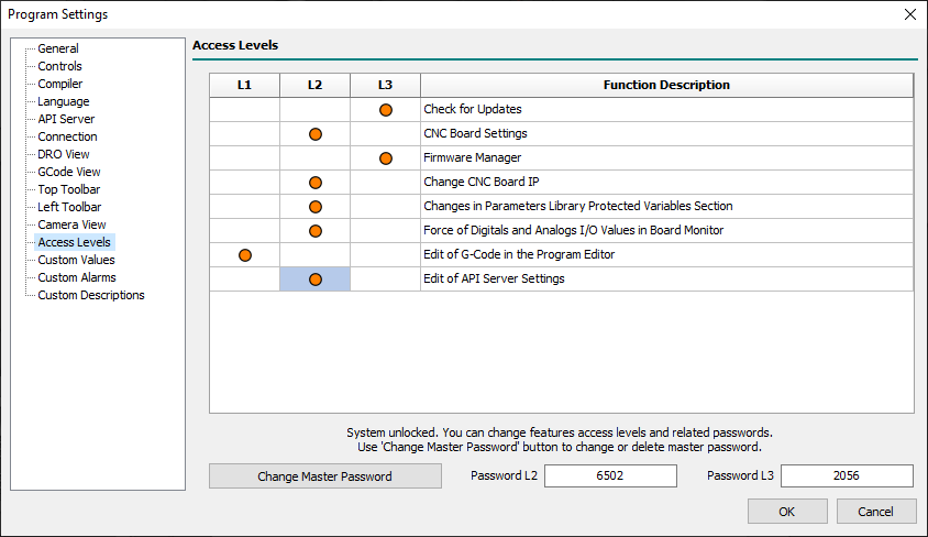
4.12 Access Levels
Through this panel, it is possible to restrict write access or disable access to some settings menus by binding everything to a password.
The system allows three access levels: L1, L2, and L3.
Level 1 is linked to the operations carried out by the machine operator.
This level does not have an associated password as it is active by default when the Control Software is started.
Level 2 could be associated with the maintenance technician of the machine who periodically may need to intervene in some aspects of the same.
Level 3 is usually the level associated with the manufacturer who is the only one who can intervene on delicate parts such as axis settings, or the firmware and software update functions.
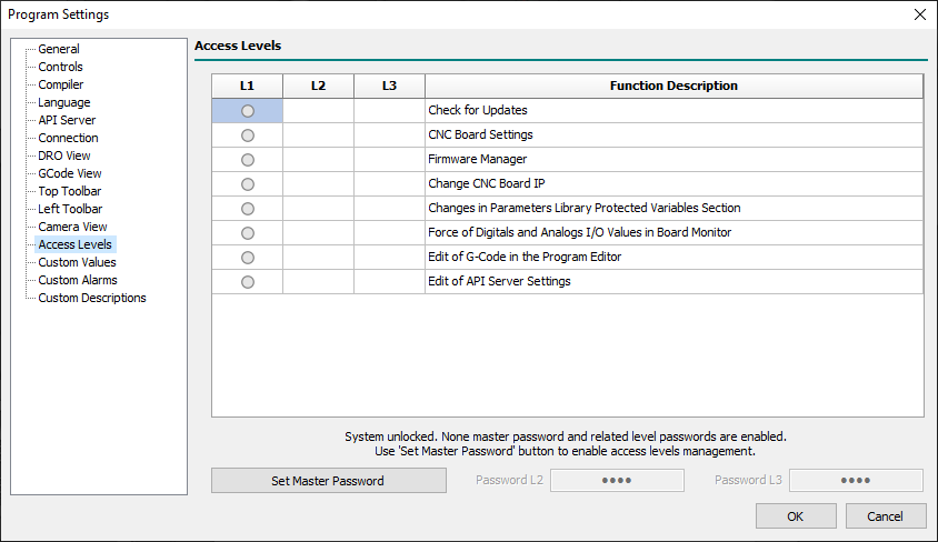
- Access Levels Table
- The table shows the functions of the Control Software that can be bound by an access level.
- The orange DOT symbol indicates to which access level every single function is associated.
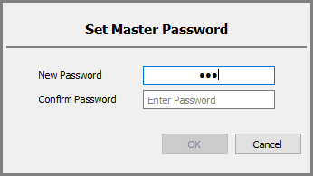
- Set Master Password
- In order to activate the system of access levels, the manufacturer of the machine must introduce a Master Key which is necessary so that it is possible to associate the functions to the various levels.
- By default, after installation, the master access key is not set and the functions are available to anyone as the access level management is not configured.
- The master key must be brought back and kept in order to be able to configure the access levels at any time.
- If the master password has never been entered, a double confirmation will be requested before accepting it:
- If a master password has already been entered and you want to change it, you must first enter the old password followed by the double-entry of the new one:
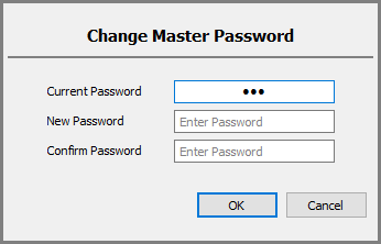
- A new password consisting of an empty string means that you want to disable the level access system.
- Password L2
- Defines the password for access level L2.
- The password can be numeric or alphanumeric.
- The password must be different from the master password or other level passwords.
- Password L3
- Defines the password for access level L3.
- The password can be numeric or alphanumeric.
- The password must be different from the master password or other level passwords.
A practical example of a typical configuration:
4.13 Custom Alarms
4.13.1 Alarms [ From Inputs ]
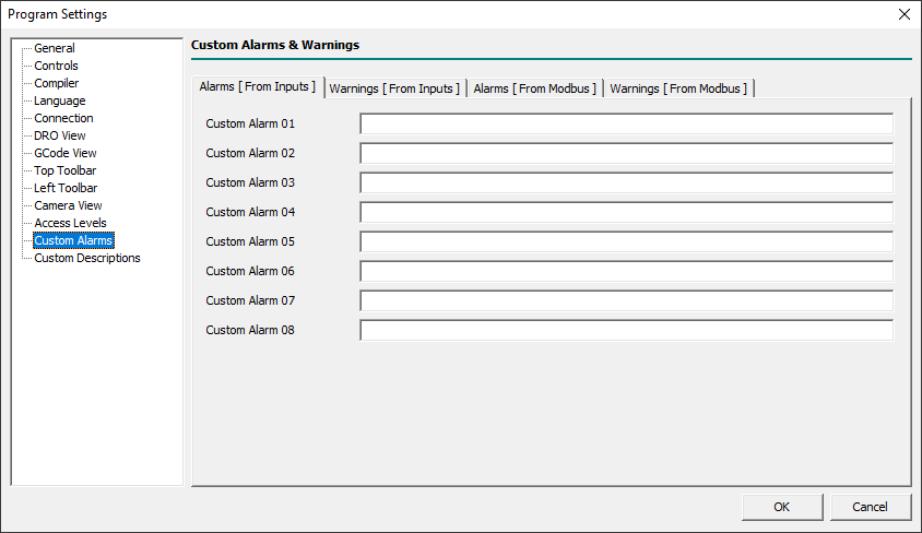
- Custom Alarm 01..08
- Xxx…
4.13.2 Warnings [ From Inputs ]
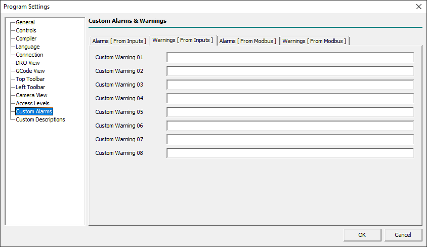
- Custom Warning 01..08
- Xxx…
4.13.3 Alarms [ From Modbus ]
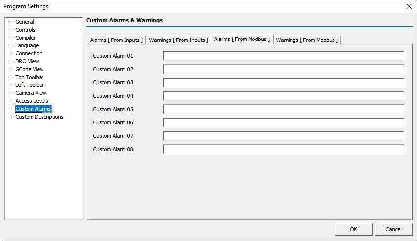
- Custom Alarm 01..08
- Xxx…
4.13.4 Warnings [ From Modbus ]

- Custom Warning 01..08
- Xxx…
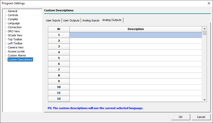
4.14 Custom Descriptions
Through this panel and related sheets, it is possible to define the custom descriptions for user inputs/outputs and analog inputs/outputs.
For the custom descriptions, only chars from the ANSI chars set are usable.
Every language supported by Control Software will have its messages so if the English language is active the showed/entered messages in the grid will be for English.
To Enter the descriptions for a different language select what in the Language panel then enter related text in the grid.
All messages are stored in the external file rosettacnc.ini, of the current machine, and they could be also edited with an external editor in the ANSI char format.
The custom descriptions will be used and shown in the Board Monitor panel reachable with the menu Setup→Board Monitor.. when the Control Software is connected with a CNC Board:
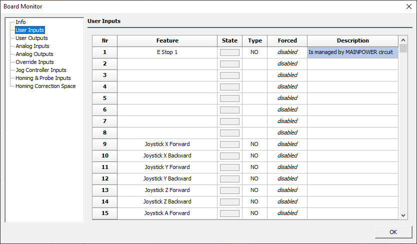
The Board Monitor is enabled to permits direct editing of the description fields in the currently active language.
4.14.1 User Inputs

This sheet permits editing of the user inputs custom descriptions.
The field Nr corresponds to the user input number (eg: 1 = user input 1).
The field Description will contain the custom description text in the currently active language.
4.14.2 User Outputs

4.14.3 Analog Inputs

4.14.4 Analog Outpus